Subaru Crosstrek Service Manual: Installation
LUBRICATION(H4DO) > Oil Level Switch
INSTALLATION
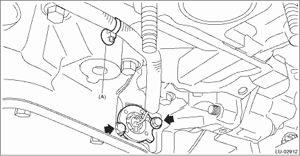
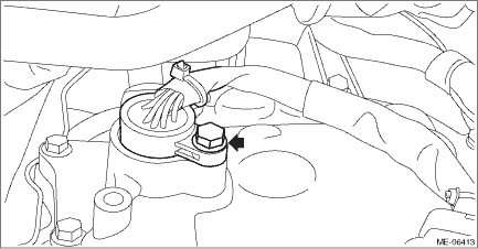
1. Install the oil level switch and the clip (A) to the oil pan upper.
NOTE:
• Use new O-rings.
• Apply a coat of engine oil to the O-rings.
Tightening torque:
6.4 N·m (0.7 kgf-m, 4.7 ft-lb)
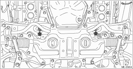
2. Install the engine mounting LH onto the engine.
Tightening torque:
35 N·m (3.6 kgf-m, 25.8 ft-lb)
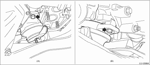
(A) | Front side | (B) | Rear side |
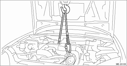
3. Lower the engine and remove the lifting device and wire ropes.
4. Remove the bolt and turn the transmission harness counterclockwise to install the transmission harness to the control valve body. (CVT model)
Tightening torque:
7 N·m (0.7 kgf-m, 5.2 ft-lb)
5. Install the bolt which holds the transmission harness stay. (CVT model)
Tightening torque:
7 N·m (0.7 kgf-m, 5.2 ft-lb)
6. Install the transmission case cover. (CVT model)
Tightening torque:
8 N·m (0.8 kgf-m, 5.9 ft-lb)
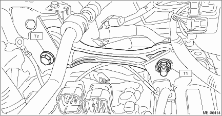
7. Install the pitching stopper.
Tightening torque:
T1: 50 N·m (5.1 kgf-m, 36.9 ft-lb)
T2: 58 N·m (5.9 kgf-m, 42.8 ft-lb)
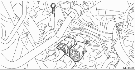
8. Connect the transmission radio ground terminal (C) to the vehicle body, and connect the bulkhead harness connector to the transmission harness connector (A) and the inhibitor harness connector (B). (CVT model)
Tightening torque:
13 N·m (1.3 kgf-m, 9.6 ft-lb)
9. Install the electric power steering gearbox. Electric Power Steering Gearbox > INSTALLATION">
10. Install the front drive shaft LH. Front Drive Shaft > INSTALLATION">
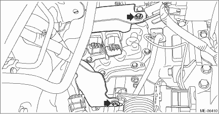
11. Install the nuts which hold the engine mounting to the front crossmember. (CVT model)
NOTE:
• Make sure that locators (A) of the engine mounting are securely inserted.
• Use a new nut.
Tightening torque:
60 N·m (6.1 kgf-m, 44.3 ft-lb)

12. Install the nuts which hold the engine mounting to the front crossmember. (MT model)
NOTE:
Use a new nut.
Tightening torque:
60 N·m (6.1 kgf-m, 44.3 ft-lb)
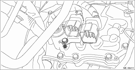
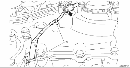
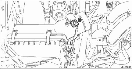
13. Connect the connector of oil level switch to the engine harness, and install the clip (A) securing the harness.
14. Install the front exhaust pipe. Front Exhaust Pipe > INSTALLATION">
15. Install the under cover.
16. Lower the vehicle.
17. Secure the air breather hose to the engine rear hanger using clip. (MT model)
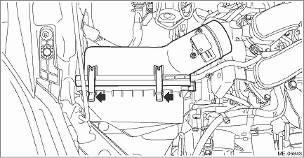
18. Install the air intake case (rear).
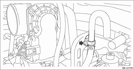
19. Install the clip (A) which secures the air flow and intake air temperature sensor harness, and connect the connector to the air flow and intake air temperature sensor.
20. Install the air intake boot. Air Intake Boot > INSTALLATION">
21. Install the air intake duct. Air Intake Duct > INSTALLATION">
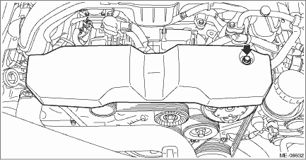
22. Install the V-belt cover.
Tightening torque:
7 N·m (0.7 kgf-m, 5.2 ft-lb)
23. Refill the engine oil. Engine Oil > REPLACEMENT">
24. Connect the battery ground terminal. NOTE">
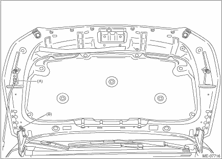
25. Change the front hood stay position from (B) to (A).
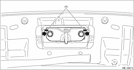
26. Install the front hood striker to the front hood by aligning the alignment marks (A), and close the front hood.
Tightening torque:
33 N·m (3.4 kgf-m, 24.3 ft-lb)
 Wiring diagram
LUBRICATION(H4DO) > Oil Level SwitchWIRING DIAGRAM• Engine electrical system Engine Electrical System > WIRING DIAGRAM">• CAN communication system CAN Communication System ...
 Removal
LUBRICATION(H4DO) > Oil Level SwitchREMOVAL1. Open the front hood, and make alignment marks (A) on the front hood striker and the front hood using a marker pen.2. Remove the front hood striker from ...
Other materials:
Removal
CONTROL SYSTEMS > AT Shift Lock Solenoid and “P” Range SwitchREMOVAL1. SOLENOID UNIT1. Remove the AT select lever. Select Lever > REMOVAL">2. Remove the spacer and gasket. Select Lever > DISASSEMBLY">3. Using a flat tip screwdriver with a thin tip, remove the h ...
Engine oil consumption
Some engine oil will be consumed while
driving. The rate of consumption can be
affected by such factors as transmission
type, driving style, terrain and temperature.
Under the following conditions, oil
consumption can be increased and thus
require refilling between maintenance
intervals:
...
Dtc c0045 incorrect vdc control module specifications
VEHICLE DYNAMICS CONTROL (VDC) (DIAGNOSTICS) > Diagnostic Procedure with Diagnostic Trouble Code (DTC)DTC C0045 INCORRECT VDC CONTROL MODULE SPECIFICATIONSDTC detecting condition:Different control module specificationTrouble symptom:• ABS does not operate.• VDC does not operate.• ...
