Subaru Crosstrek Service Manual: Installation
LIGHTING SYSTEM > Headlight Assembly
INSTALLATION
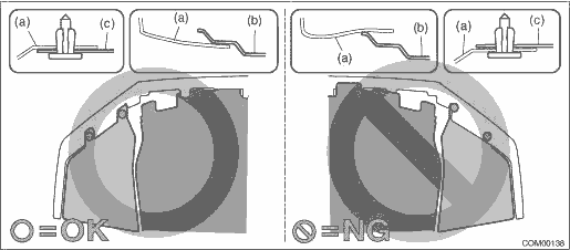
CAUTION:
Install so that the front end of the under cover (b) comes inside the bumper face - front (a), and the front end of the mud guard (c) comes outside the bumper face - front (a).
1. Install each part in the reverse order of removal.
Tightening torque:
Light assembly - head: 7.5 N·m (0.76 kgf-m, 5.5 ft-lb)
2. Secure the flange section of the bumper face - front to the bracket - front bumper side.
3. Adjust the headlight beam and fog light beam.
• Adjust the headlight beam. Headlight Assembly > ADJUSTMENT">
• Adjust the fog light beam. Front Fog Light Assembly > ADJUSTMENT">
 Disassembly
LIGHTING SYSTEM > Headlight AssemblyDISASSEMBLY1. HID HEADLIGHT BALLASTCAUTION:Do not leave the light assembly - head without the ballast - headlight for a long time. Dust, moisture, etc. entering ...
 Headlight bulb
...
Other materials:
Clock
To adjust the time shown by the clock,
press the "+" button or "−" button. If you
press the "+" button, the indicated time will
change in one-minute increments. If you
press the "−" button, the indicated time will
change in one-minute decrements. If you
keep the button pressed, ...
Removal
LIGHTING SYSTEM > Front Side Marker Light BulbREMOVAL1. Disconnect the ground cable from battery. NOTE">2. Turn the steering wheel in the opposite direction from the parts to be removed. Then remove the clips and turn over the mud guard - front.3. Remove the bulb socket and front side ma ...
Dtc u0416 invalid data received from vehicle dynamics control module
POWER ASSISTED SYSTEM (POWER STEERING) (DIAGNOSTICS) > Diagnostic Procedure with Diagnostic Trouble Code (DTC)DTC U0416 INVALID DATA RECEIVED FROM VEHICLE DYNAMICS CONTROL MODULENOTE:Refer to “LAN SYSTEM” for diagnostic procedure. Basic Diagnostic Procedure"> ...
