Subaru Crosstrek Service Manual: Installation
FUEL INJECTION (FUEL SYSTEMS)(H4DO) > Fuel Sub Level Sensor
INSTALLATION
1. Install the fuel sub level sensor to the fuel tank.
(1) Make sure the sealing portion is free from fuel or foreign matter before installation.
(2) Align the cutout (B) as shown in the figure, and install the fuel sub level sensor upper plate cushion to the fuel sub level sensor upper plate.
(3) Align the cutout of the fuel sub level sensor upper plate with the protrusion (B) of the fuel sub level sensor as shown in the figure, and install the fuel sub level sensor upper plate from the upper side of the fuel sub level sensor.
(4) Install the gasket from the lower side of the fuel sub level sensor so that the protrusion (B) of the fuel sub level sensor and the protrusion (A) of the gasket are positioned as shown in the figure.
NOTE:
Use a new gasket.
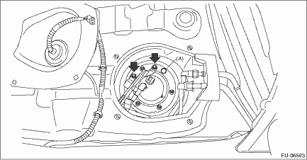
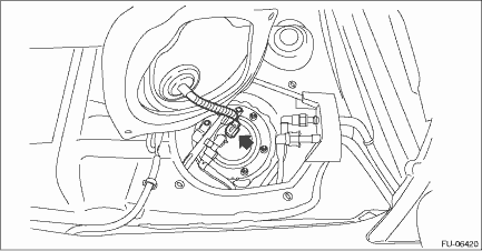
(5) Install the fuel sub level sensor to the fuel tank in the direction shown in the figure, and tighten the nuts to the specified torque in the order as shown in the figure.
CAUTION:
Set the arm and float of the fuel sub level sensor while paying attention to prevent them from contacting the fuel tank. If the arm of the fuel sub level sensor is bent, the fuel gauge may not read correctly.
Tightening torque:
4.4 N·m (0.4 kgf-m, 3.2 ft-lb)
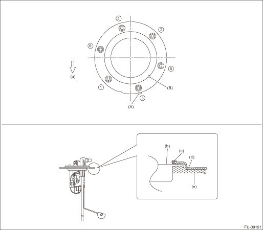
(a) | Front side of vehicle | (c) | Fuel sub level sensor upper plate cushion | (e) | Gasket |
(b) | Fuel sub level sensor | (d) | Fuel sub level sensor upper plate |
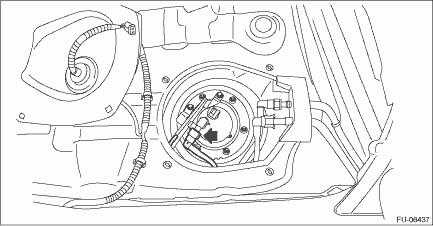
2. Install the fuel sub level sensor protector, and install the rubber cap (A).
Tightening torque:
4.4 N·m (0.4 kgf-m, 3.2 ft-lb)
3. Connect the quick connector of the jet pump tube.
CAUTION:
• Check that there is no damage or dust on the quick connector. If necessary, clean the seal surface of the pipe.
• When connecting the quick connector, make sure to insert it all the way in before locking the slider.
• When it is difficult to lock the slider, check that the connector is fully inserted.
• After locking the slider, check again that the quick connector is securely connected.
NOTE:
Connect the quick connector as shown in the figure.
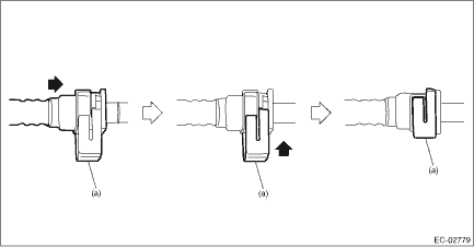
(a) | Slider |
4. Connect the connector to the fuel sub level sensor.
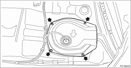
5. Install the service hole cover of fuel sub level sensor.
6. Install the rear seat cushion. Rear Seat > INSTALLATION">
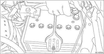
7. Connect the battery ground terminal.
 Removal
FUEL INJECTION (FUEL SYSTEMS)(H4DO) > Fuel Sub Level SensorREMOVALWARNING:Place “NO OPEN FLAMES” signs near the working area.CAUTION:• Be careful not to spill fuel.• Catch t ...
 Fuel tank
...
Other materials:
Assembly
CONTROL SYSTEMS > Select LeverASSEMBLY1. Clean all the parts before assembly.2. Apply Multemp D or equivalent to the sliding portion of each part.3. Assemble in the reverse order of disassembly.NOTE:Insert the solenoid unit terminals to the harness connector.(A)Solenoid unit (color code: blue)(B) ...
Fuel requirements
The Subaru Ascent engine is engineered to operate efficiently on unleaded gasoline
with an octane rating of at least 87 AKI (90 RON). Using the correct fuel ensures
optimal performance, fuel economy, and engine longevity.
NOTE
When towing with the Subaru Ascent, it is advisable to use higher-o ...
Component
MANUAL TRANSMISSION AND DIFFERENTIAL(5MT) > General DescriptionCOMPONENT1. TRANSMISSION CASE(1)Transmission case ASSY(7)Pitching stopper bracketTightening torque: N·m (kgf-m, ft-lb)(2)Gasket(8)Oil level gaugeT:44 (4.5, 32.5) (aluminum gasket, silver)(3)Drain plug(9)Harness clip 70 (7.1, 51 ...
