Subaru Crosstrek Service Manual: Installation
EXTERIOR BODY PANELS > Front Hood
INSTALLATION
CAUTION:
The hood COMPL - front is heavy. When removing or installing the hinge COMPL - front hood, be sure to work in a group of two or more.
1. To install the insulator - front hood and the seal - front duct, follow the removal procedure in the reverse order.
2. Align the alignment marks (A), and install the striker - front hood to the hood COMPL - front.
CAUTION:
When installing the striker - front hood, make sure that the front and rear sides are positioned in a correct direction.
Tightening torque:
33 N·m (3.36 kgf-m, 24.3 ft-lb)
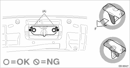
(A) | Alignment mark | F | Front side of vehicle |
NOTE:
It is not necessary to adjust the striker - front hood because there is no span of adjustable range.
3. Install the hinge COMPL - front hood to the vehicle body. (When the hinge COMPL - front hood is removed)
4. Temporarily install the hood COMPL - front to the hinge COMPL - front hood.
NOTE:
When installing the hood COMPL - front, make sure that a uniform clearance is created around it.
5. Adjust the clearance around the hood COMPL - front. Front Hood > ADJUSTMENT">
6. Tighten the bolts and nuts of the hinge COMPL - front hood.
Tightening torque:
25 N·m (2.55 kgf-m, 18.4 ft-lb)
7. Install each part of the hood COMPL - front in the reverse order of removal.
• Insulator - front hood
• Seal - front duct
 Removal
EXTERIOR BODY PANELS > Front HoodREMOVAL1. FRONT HOOD PANELCAUTION:The hood COMPL - front is heavy. When removing or installing the hinge COMPL - front hood, be sure to work in a group of two or mo ...

Other materials:
Main screen
To access the main screen in the Subaru Ascent, simply touch
(HOME). This action instantly brings up the central interface, where all primary
vehicle systems and settings are organized for quick and intuitive access.
Within this Owner's Manual, only selected configuration sections are ...
Installation
BRAKE > Front Disc Brake AssemblyINSTALLATIONNOTE:Before installation, remove mud and foreign matter from the caliper body assembly and support - front disc brake.1. Check each part. Front Disc Brake Assembly > INSPECTION">2. Apply a thin coat of grease to the support - front disc bra ...
Adjustment
BRAKE > Stop Light SwitchADJUSTMENT1. BULB TYPECAUTION:• Turn the stop light switch clockwise when installing so that it can return backward by approximately 1 mm (0.04 in) and clearance is automatically adjusted.• If it is hard to turn the switch, reduce the switch pushing force and ...
