Subaru Crosstrek Service Manual: Installation
EMISSION CONTROL (AUX. EMISSION CONTROL DEVICES)(H4DO) > Canister
INSTALLATION
1. Install the canister to the vehicle using bolts and nuts.
Tightening torque:
7.5 N·m (0.8 kgf-m, 5.5 ft-lb)
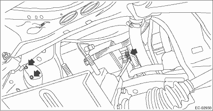
2. Install the drain tube (A), vent tube (B) and purge tube (C) to the canister.
CAUTION:
• Check that there is no damage or dust on the quick connector. If necessary, clean the seal surface of the pipe.
• Make sure that the quick connector is securely connected.
NOTE:
Install the quick connector as shown in the figure.
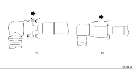
(a) | Drain tube and vent tube | (b) | Purge tube |

3. Lift up the transmission jack gradually, and set the rear differential to the rear sub frame assembly.
NOTE:
When inserting the stud bolt into the bushing portion of the rear sub frame assembly, adjust the angle and location of transmission jack and jack stand.
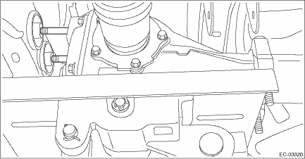
4. Temporarily tighten the self-locking nuts which hold the rear differential to the rear sub frame assembly.
NOTE:
Use a new self-locking nut.

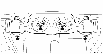
5. Set the rear differential member to the rear sub frame assembly and rear differential, and temporarily tighten the self-lock nuts which secure the rear differential member to the rear sub frame assembly and rear differential.
NOTE:
Use a new self-locking nut.
6. Remove the transmission jack from the rear differential.
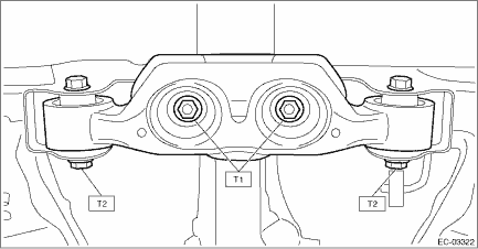
7. Tighten the self-locking nuts which secure the rear differential member to the rear sub frame assembly and rear differential.
Tightening torque:
T1: 50 N·m (5.1 kgf-m, 36.9 ft-lb)
T2: 110 N·m (11.2 kgf-m, 81.1 ft-lb)
8. Tighten the self-locking nuts which secure the rear differential to the rear sub frame assembly.
Tightening torque:
70 N·m (7.1 kgf-m, 51.6 ft-lb)
9. Install the propeller shaft. Propeller Shaft > INSTALLATION">
10. Install the rear exhaust pipe. Rear Exhaust Pipe > INSTALLATION">
11. Lower the vehicle.
 Removal
EMISSION CONTROL (AUX. EMISSION CONTROL DEVICES)(H4DO) > CanisterREMOVAL1. Lift up the vehicle.2. Remove the rear exhaust pipe. Rear Exhaust Pipe > REMOVAL">3. Remove the propeller shaf ...
 Drain separator
...
Other materials:
To decrease the speed (by brake pedal)
1. Depress the brake pedal to release
cruise control temporarily.
2. When the speed decreases to the
desired speed, press the "RES/SET"
switch to the "SET" side once. Now the
desired speed is set and the vehicle will
keep running at that speed without depressing
the accelerator pedal.
Cr ...
Warning chimes and warning indicator of the keyless access with push-button
start system (if equipped)
Access key warning indicator (type A)
Access key warning indicator (type B)
The warning chime and the access key
warning indicator are used for the following
purposes.
Minimizing improper operations when
using the keyless access with push-button
start system
Helping protect you ...
Removal
POWER ASSISTED SYSTEM (POWER STEERING) > Power Steering Control ModuleREMOVAL1. Disconnect the ground cable from battery. NOTE">2. Remove the power steering control module.(1) Disconnect the connector of the power steering control module.(2) Remove the nuts, and remove the power steering ...
