Subaru Crosstrek Service Manual: Dtc p0328 knock/combustion vibration sensor 1 circuit high bank 1 or single sensor
ENGINE (DIAGNOSTICS)(H4DO) > Diagnostic Procedure with Diagnostic Trouble Code (DTC)
DTC P0328 KNOCK/COMBUSTION VIBRATION SENSOR 1 CIRCUIT HIGH BANK 1 OR SINGLE SENSOR
DTC DETECTING CONDITION:
Immediately at fault recognition
TROUBLE SYMPTOM:
• Poor driving performance
• Knocking occurs
CAUTION:
After servicing or replacing faulty parts, perform Clear Memory Mode Clear Memory Mode > OPERATION"> , and Inspection Mode Inspection Mode > PROCEDURE">.
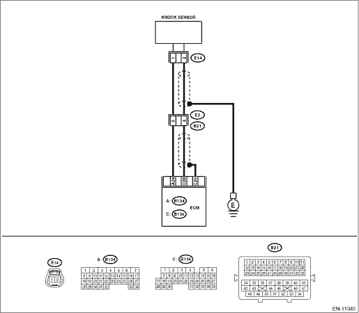
WIRING DIAGRAM:
Engine electrical system Engine Electrical System">
| STEP | CHECK | YES | NO |
1.CHECK HARNESS BETWEEN ECM AND KNOCK SENSOR CONNECTOR.
1) Turn the ignition switch to OFF.
2) Disconnect the connector from ECM.
3) Measure the resistance between ECM connectors.
Connector & terminal
(B136) No. 28 — (B134) No. 29:
Is the resistance 600 k? or more?
Diagnostic Procedure with Diagnostic Trouble Code (DTC) > DTC P0328 KNOCK/COMBUSTION VIBRATION SENSOR 1 CIRCUIT HIGH BANK 1 OR SINGLE SENSOR">Go to Step 2.
Repair the poor contact of ECM connector.
2.CHECK KNOCK SENSOR.
1) Disconnect the connector from the knock sensor.
2) Measure the resistance between knock sensor terminals.
Terminals
No. 1 — No. 2:
Is the resistance 600 k? or more?
Replace the knock sensor. Knock Sensor">
Repair the harness and connector.
NOTE:
In this case, repair the following item:
• Open circuit in harness between ECM connector and knock sensor connector
• Poor contact of knock sensor connector
• Poor contact of coupling connector
1. OUTLINE OF DIAGNOSIS
Detect the open or short circuit of knock sensor.
Judge as NG if out of specification.
2. COMPONENT DESCRIPTION
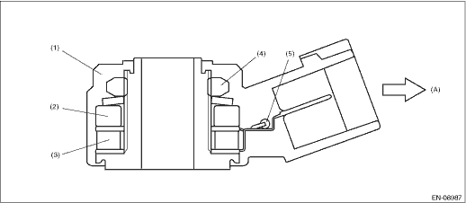
(A) | To knock sensor harness | ||||
(1) | Case | (3) | Piezoelectric element | (5) | Resistance |
(2) | Weight | (4) | Nut |
3. EXECUTION CONDITION
Secondary Parameters | Execution condition |
None |
4. GENERAL DRIVING CYCLE
Always perform the diagnosis continuously.
5. DIAGNOSTIC METHOD
If the duration of time while the following conditions are met is longer than the time indicated, judge as NG.
Malfunction Criteria | Threshold Value |
Output voltage | ≥ 4.838 V |
Time Needed for Diagnosis: 1000 ms
Malfunction Indicator Light Illumination: Illuminates as soon as a malfunction occurs.
 Dtc p0327 knock/combustion vibration sensor 1 circuit low bank 1 or single sensor
ENGINE (DIAGNOSTICS)(H4DO) > Diagnostic Procedure with Diagnostic Trouble Code (DTC)DTC P0327 KNOCK/COMBUSTION VIBRATION SENSOR 1 CIRCUIT LOW BANK 1 OR SINGLE SENSORDTC DETECTING CONDITION:Immediat ...
 Dtc p0335 crankshaft position sensor "a" circuit
ENGINE (DIAGNOSTICS)(H4DO) > Diagnostic Procedure with Diagnostic Trouble Code (DTC)DTC P0335 CRANKSHAFT POSITION SENSOR "A" CIRCUITDTC DETECTING CONDITION:Immediately at fault recognitio ...
Other materials:
Forced drive
SUNROOF/T-TOP/CONVERTIBLE TOP (SUNROOF) > Glass LidFORCED DRIVEIf the lid assembly - sunroof does not operate or the motor assembly is not supplied with power, move the lid assembly - sunroof using the hexagon wrench.Preparation tool:Hexagon wrench: width across flat 4 mm (0.16 in)CAUTION:After a ...
Fuel Procedure
FUEL INJECTION (FUEL SYSTEMS)(H4DO) > FuelPROCEDURE1. RELEASING OF FUEL PRESSUREWARNING:Place “NO OPEN FLAMES” signs near the working area.CAUTION:Be careful not to spill fuel.1. Remove the fuse of fuel pump from main fuse box.2. Start the engine and run it until it stalls.3. After th ...
Diagnostic procedure for subaru select monitor communication Communication for initializing impossible
CONTINUOUSLY VARIABLE TRANSMISSION (DIAGNOSTICS) > Diagnostic Procedure for Subaru Select Monitor CommunicationCOMMUNICATION FOR INITIALIZING IMPOSSIBLEDiagnosis:Defective harness connectorTrouble symptom:Subaru Select Monitor communication failureCAUTION:Use the check board when measuring the TC ...
