Subaru Crosstrek Service Manual: Dtc p0335 crankshaft position sensor "a" circuit
ENGINE (DIAGNOSTICS)(H4DO) > Diagnostic Procedure with Diagnostic Trouble Code (DTC)
DTC P0335 CRANKSHAFT POSITION SENSOR "A" CIRCUIT
DTC DETECTING CONDITION:
Immediately at fault recognition
TROUBLE SYMPTOM:
• Engine stall
• Failure of engine to start
CAUTION:
After servicing or replacing faulty parts, perform Clear Memory Mode Clear Memory Mode > OPERATION"> , and Inspection Mode Inspection Mode > PROCEDURE">.
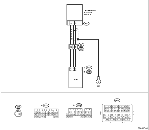
WIRING DIAGRAM:
Engine electrical system Engine Electrical System">
| STEP | CHECK | YES | NO |
1.CHECK INSTALLATION CONDITION OF CRANKSHAFT POSITION SENSOR.
Is the crankshaft position sensor installation bolt tightened securely?
Diagnostic Procedure with Diagnostic Trouble Code (DTC) > DTC P0335 CRANKSHAFT POSITION SENSOR "A" CIRCUIT">Go to Step 2.
Tighten the crankshaft position sensor installation bolt securely. Crankshaft Position Sensor > INSTALLATION">
2.CHECK CRANKSHAFT POSITION SENSOR.
1) Turn the ignition switch to OFF.
2) Remove the crankshaft position sensor.
3) Measure the resistance between terminals of crankshaft position sensor.
Terminals
No. 1 — No. 2:
Is the resistance between 1 and 4 k??
Diagnostic Procedure with Diagnostic Trouble Code (DTC) > DTC P0335 CRANKSHAFT POSITION SENSOR "A" CIRCUIT">Go to Step 3.
Replace the crankshaft position sensor. Crankshaft Position Sensor">
3.CHECK HARNESS BETWEEN ECM AND CRANKSHAFT POSITION SENSOR CONNECTOR.
1) Disconnect the connector from ECM.
2) Measure the resistance of harness between ECM connector and crankshaft position sensor connector.
Connector & terminal
(B136) No. 16 — (E10) No. 1:
(B136) No. 27 — (E10) No. 2:
Is the resistance less than 1 ??
Repair the poor contact of ECM and crankshaft position sensor connector.
Repair the harness and connector.
NOTE:
In this case, repair the following item:
• Open circuit in harness between ECM connector and crankshaft position sensor connector
• Poor contact of coupling connector
1. OUTLINE OF DIAGNOSIS
Detect the open or short circuit of the crankshaft position sensor.
Judge as NG when the crank signal is not input even though the starter was rotated.
2. COMPONENT DESCRIPTION
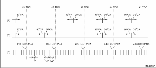
(A) | Camshaft signal (RH) | (B) | Camshaft signal (LH) | (C) | Crankshaft signal |
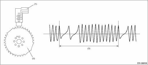
(1) | Crankshaft position sensor | (2) | Crankshaft position sensor plate | (3) | Crankshaft half-turn |
3. EXECUTION CONDITION
Secondary Parameters | Execution condition |
Battery voltage | ≥ 8 V |
4. GENERAL DRIVING CYCLE
Always perform the diagnosis continuously.
5. DIAGNOSTIC METHOD
If the duration of time while the following conditions are met is longer than the time indicated, judge as NG.
Malfunction Criteria | Threshold Value |
Crankshaft position sensor signal | Not detected |
Time Needed for Diagnosis: 3000 ms
Malfunction Indicator Light Illumination: Illuminates as soon as a malfunction occurs.
 Dtc p0328 knock/combustion vibration sensor 1 circuit high bank 1 or single sensor
ENGINE (DIAGNOSTICS)(H4DO) > Diagnostic Procedure with Diagnostic Trouble Code (DTC)DTC P0328 KNOCK/COMBUSTION VIBRATION SENSOR 1 CIRCUIT HIGH BANK 1 OR SINGLE SENSORDTC DETECTING CONDITION:Immedia ...
 Dtc p0336 crankshaft position sensor "a" circuit range/performance
ENGINE (DIAGNOSTICS)(H4DO) > Diagnostic Procedure with Diagnostic Trouble Code (DTC)DTC P0336 CRANKSHAFT POSITION SENSOR "A" CIRCUIT RANGE/PERFORMANCEDTC detecting condition:Detected when ...
Other materials:
Removal
GLASS/WINDOWS/MIRRORS > Rear Quarter GlassREMOVAL1. Disconnect the ground cable from battery. NOTE">2. Remove the trim panel - rear pillar UPR. Rear Quarter Trim > REMOVAL">3. Remove the glass - rear quarter in the same procedure as for the glass - front window. Windshield G ...
Tire care - maintenance and safety practices
For reliable performance of your Subaru Ascent, inspect the tires ежедневно
or before each drive to ensure they are free from serious damage, embedded objects
such as nails or stones, and any visible defects. At the same time, carefully
examine the tread pattern for signs of une ...
Glossary of tire terminology
Accessory weight
The combined weight (in excess of
those standard items which may be
replaced) of automatic transmission,
power steering, power brakes,
power windows, power seats, radio,
and heater, to the extent that these
items are available as factory-installed
equipment (whether ins ...
