Subaru Crosstrek Service Manual: Dtc p0336 crankshaft position sensor "a" circuit range/performance
ENGINE (DIAGNOSTICS)(H4DO) > Diagnostic Procedure with Diagnostic Trouble Code (DTC)
DTC P0336 CRANKSHAFT POSITION SENSOR "A" CIRCUIT RANGE/PERFORMANCE
DTC detecting condition:
Detected when two consecutive driving cycles with fault occur.
Trouble symptom:
• Engine stall
• Failure of engine to start
CAUTION:
After servicing or replacing faulty parts, perform Clear Memory Mode Clear Memory Mode > OPERATION"> , and Inspection Mode Inspection Mode > PROCEDURE">.
| STEP | CHECK | YES | NO |
1.CHECK CONDITION OF CRANKSHAFT POSITION SENSOR.
Turn the ignition switch to OFF.
Is the crankshaft position sensor installation bolt tightened securely?
Diagnostic Procedure with Diagnostic Trouble Code (DTC) > DTC P0336 CRANKSHAFT POSITION SENSOR "A" CIRCUIT RANGE/PERFORMANCE">Go to Step 2.
Tighten the crankshaft position sensor installation bolt securely. Crankshaft Position Sensor > INSTALLATION">
2.CHECK CRANKSHAFT POSITION SENSOR PLATE.
Is there crack or damage in the crankshaft position sensor plate teeth?
Replace the crankshaft position sensor plate. Cylinder Block">
Diagnostic Procedure with Diagnostic Trouble Code (DTC) > DTC P0336 CRANKSHAFT POSITION SENSOR "A" CIRCUIT RANGE/PERFORMANCE">Go to Step 3.
3.CHECK INSTALLATION CONDITION OF TIMING CHAIN.
Turn the crankshaft using ST, and align the alignment mark on crank sprocket with alignment mark on cylinder block.
Is the timing chain dislocated from its proper position?
Correct the installation condition of timing chain. Timing Chain Assembly">
Replace the crankshaft position sensor. Crankshaft Position Sensor">
1. OUTLINE OF DIAGNOSIS
Detect for faults in crankshaft position sensor output properties.
Judge as NG when there is a problem in the number of crankshaft signals for every revolution of crankshaft.
2. COMPONENT DESCRIPTION
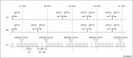
(A) | Camshaft signal (RH) | (B) | Camshaft signal (LH) | (C) | Crankshaft signal |
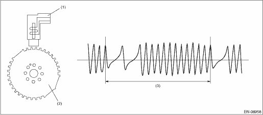
(1) | Crankshaft position sensor | (2) | Crankshaft position sensor plate | (3) | Crankshaft half-turn |
3. EXECUTION CONDITION
Secondary Parameters | Execution condition |
Battery voltage | ≥ 8 V |
4. GENERAL DRIVING CYCLE
Always perform the diagnosis continuously.
5. DIAGNOSTIC METHOD
Judge as NG when the following conditions are established.
Malfunction Criteria | Threshold Value |
Amount of crank sensor signal during 1 rev of crankshaft | Not = 30 |
Time Needed for Diagnosis: 10 time(s) engine revs.
Malfunction Indicator Light Illumination: Illuminates when malfunction occurs in 2 continuous driving cycles.
 Dtc p0335 crankshaft position sensor "a" circuit
ENGINE (DIAGNOSTICS)(H4DO) > Diagnostic Procedure with Diagnostic Trouble Code (DTC)DTC P0335 CRANKSHAFT POSITION SENSOR "A" CIRCUITDTC DETECTING CONDITION:Immediately at fault recognitio ...
 Dtc p0340 camshaft position sensor "a" circuit bank 1 or single sensor
ENGINE (DIAGNOSTICS)(H4DO) > Diagnostic Procedure with Diagnostic Trouble Code (DTC)DTC P0340 CAMSHAFT POSITION SENSOR "A" CIRCUIT BANK 1 OR SINGLE SENSORDTC DETECTING CONDITION:Immediate ...
Other materials:
Installation
HVAC SYSTEM (HEATER, VENTILATOR AND A/C) > Heater DuctINSTALLATIONCAUTION:Before handling the airbag system components, refer to “CAUTION” of “General Description” in “AIRBAG SYSTEM”. General Description > CAUTION">Install each part in the reverse o ...
Removal
EXTERIOR/INTERIOR TRIM > Rear Quarter TrimREMOVAL1. CROSSTREK MODELCAUTION:• Before handling the airbag system components, refer to “CAUTION” of “General Description” in “AIRBAG SYSTEM”. General Description > CAUTION">• Airbag system sat ...
Operation
Blind Spot Detection/Rear Cross Traffic Alert (DIAGNOSTICS) > Subaru Select MonitorOPERATION• For detailed operation procedures, refer to “Application help”.• When the radar sensor cannot communicate with Subaru Select Monitor, perform “COMMUNICATION FOR INITIALIZING ...
