Subaru Crosstrek Service Manual: Assembly
STARTING/CHARGING SYSTEMS(H4DO) > Starter
ASSEMBLY
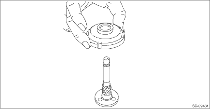
1. Apply grease to the shaft sliding surfaces of the internal gear assembly.
Grease:
Multemp #6129 or equivalent
2. Assemble the shaft to the internal gear assembly.
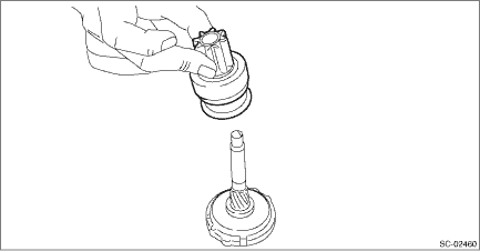
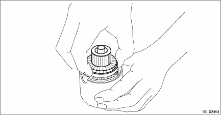
3. Assemble the overrunning clutch as follows:
(1) Apply grease to the spline portion of the shaft.
Grease:
Multemp #6129 or equivalent
(2) Install the overrunning clutch to shaft.
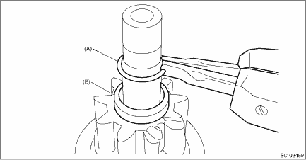
(3) Pass stopper (B) through the shaft assembly, and attach snap ring (A).
NOTE:
Use new stoppers and snap rings.
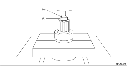
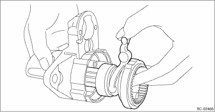
(4) Using a press, pressure fit stopper (B) into snap ring (A).
4. Assemble the overrunning clutch, internal gear assembly, shaft and shift lever as a single unit into the starter housing assembly.
NOTE:
Apply grease to the moving parts of the shift lever.
Grease:
Multemp #6129 or equivalent
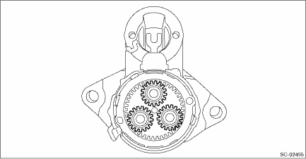
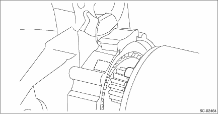
5. Apply grease to the inside of the internal gear assembly and pinion gear, and attach the pinion gear to the internal gear assembly.
NOTE:
• Apply grease evenly to the contact surfaces of each gear.
• Be careful that no debris becomes attached.
Grease:
Molykote® AG650 or equivalent
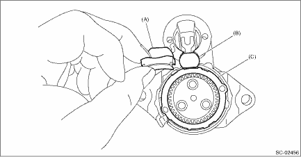
6. Install seal rubber (A), plate (B), and seal rubber (C).
7. Assemble the armature assembly to the yoke assembly.
8. Attach the armature assembly and yoke assembly to the starter housing assembly together as a single unit.
NOTE:
As shown in the figure, match the protrusion of the yoke assembly to the cut out of the starter housing assembly.
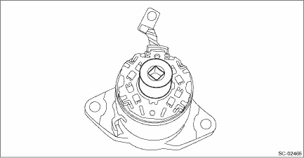
9. Use an appropriate tool (such as correctly sized socket wrenches) and attach the brush holder assembly to the armature assembly.
NOTE:
Be careful not to damage the brushes.
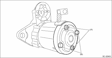
10. Secure starter cover assembly to the brush holder assembly with screws (A).
Tightening torque:
1.4 N·m (0.1 kgf-m, 1.0 ft-lb)
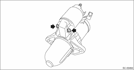
11. Tighten through bolts (B) on both sides.
Tightening torque:
6 N·m (0.6 kgf-m, 4.4 ft-lb)
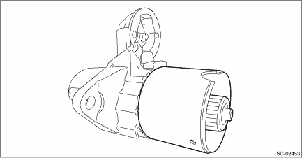
12. Attach the magnet switch assembly to the starter housing assembly.
Tightening torque:
7.5 N·m (0.8 kgf-m, 5.5 ft-lb)
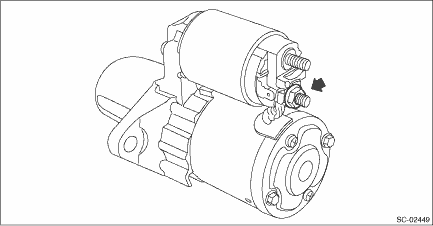
13. Attach the cable to the terminal M of the magnet switch assembly, and secure with nuts.
Tightening torque:
10 N·m (1.0 kgf-m, 7.4 ft-lb)
 Starter
...
 Removal
STARTING/CHARGING SYSTEMS(H4DO) > StarterREMOVAL1. Disconnect the ground cable from battery. NOTE">2. Remove the clip (A) from the air intake boot.3. Loosen the clamp (B) securing the air ...
Other materials:
Refrigerant recovery procedure Procedure
HVAC SYSTEM (HEATER, VENTILATOR AND A/C) > Refrigerant Recovery ProcedurePROCEDURECAUTION:• During operation, be sure to wear protective goggles and protective gloves.• Connect the refrigerant recovery system with the manifold gauge set to discharge the refrigerant from the A/C system ...
Tire pressure warning light is 25 times blinking and turn on
TIRE PRESSURE MONITORING SYSTEM (DIAGNOSTICS) > Tire Pressure Warning Light / Trouble Indicator Light Illumination PatternTIRE PRESSURE WARNING LIGHT IS 25 TIMES BLINKING AND TURN ONDetecting condition:• Defective TPMS & keyless entry CM or TPMS CM• Defective harness• Transm ...
Installation
EyeSight > Stereo CameraINSTALLATIONCAUTION:• Do not remove the protective cover until just before installing the stereo camera cover assembly. Using the bolt and nut, install the stereo camera with the protective cover attached, connect the connectors, and then remove the protective cover. ...
