Subaru Crosstrek Service Manual: Dtc p0340 camshaft position sensor "a" circuit bank 1 or single sensor
ENGINE (DIAGNOSTICS)(H4DO) > Diagnostic Procedure with Diagnostic Trouble Code (DTC)
DTC P0340 CAMSHAFT POSITION SENSOR "A" CIRCUIT BANK 1 OR SINGLE SENSOR
DTC DETECTING CONDITION:
Immediately at fault recognition
TROUBLE SYMPTOM:
• Engine stall
• Failure of engine to start
CAUTION:
After servicing or replacing faulty parts, perform Clear Memory Mode Clear Memory Mode > OPERATION"> , and Inspection Mode Inspection Mode > PROCEDURE">.
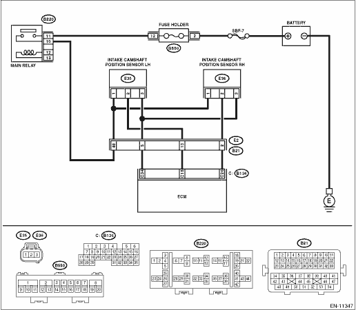
WIRING DIAGRAM:
Engine electrical system Engine Electrical System">
| STEP | CHECK | YES | NO |
1.CHECK POWER SUPPLY OF CAMSHAFT POSITION SENSOR.
1) Turn the ignition switch to OFF.
2) Disconnect the connector from camshaft position sensor.
3) Turn the ignition switch to ON.
4) Measure the voltage between camshaft position sensor connector and engine ground.
Connector & terminal
(E36) No. 1 (+) — Engine ground (−):
Is the voltage 10 V or more?
Diagnostic Procedure with Diagnostic Trouble Code (DTC) > DTC P0340 CAMSHAFT POSITION SENSOR "A" CIRCUIT BANK 1 OR SINGLE SENSOR">Go to Step 2.
Repair the harness and connector.
NOTE:
In this case, repair the following item:
• Open circuit or short circuit to ground in harness between main relay connector and camshaft position sensor connector
• Poor contact of coupling connector
2.CHECK HARNESS BETWEEN ECM AND CAMSHAFT POSITION SENSOR CONNECTOR.
1) Turn the ignition switch to OFF.
2) Disconnect the connector from ECM.
3) Measure the resistance between ECM connector and camshaft position sensor connector.
Connector & terminal
(B136) No. 26 — (E36) No. 2:
(B136) No. 34 — (E36) No. 3:
Is the resistance less than 1 ??
Diagnostic Procedure with Diagnostic Trouble Code (DTC) > DTC P0340 CAMSHAFT POSITION SENSOR "A" CIRCUIT BANK 1 OR SINGLE SENSOR">Go to Step 3.
Repair the harness and connector.
NOTE:
In this case, repair the following item:
• Open circuit in harness between ECM connector and camshaft position sensor connector
• Poor contact of coupling connector
3.CHECK HARNESS BETWEEN ECM AND CAMSHAFT POSITION SENSOR CONNECTOR.
Measure the resistance between camshaft position sensor connector and engine ground.
Connector & terminal
(E36) No. 2 — Engine ground:
Is the resistance 1 M? or more?
Diagnostic Procedure with Diagnostic Trouble Code (DTC) > DTC P0340 CAMSHAFT POSITION SENSOR "A" CIRCUIT BANK 1 OR SINGLE SENSOR">Go to Step 4.
Repair short circuit to ground in harness between ECM connector and camshaft position sensor connector.
4.CHECK HARNESS BETWEEN ECM AND CAMSHAFT POSITION SENSOR CONNECTOR.
Measure the voltage between camshaft position sensor connector and engine ground.
Connector & terminal
(E36) No. 2 (+) — Engine ground (−):
Is the voltage 5 V or more?
Repair the short circuit to power in the harness between ECM connector and camshaft position sensor connector.
Diagnostic Procedure with Diagnostic Trouble Code (DTC) > DTC P0340 CAMSHAFT POSITION SENSOR "A" CIRCUIT BANK 1 OR SINGLE SENSOR">Go to Step 5.
5.CHECK CONDITION OF CAMSHAFT POSITION SENSOR.
Is the camshaft position sensor installation bolt tightened securely?
Diagnostic Procedure with Diagnostic Trouble Code (DTC) > DTC P0340 CAMSHAFT POSITION SENSOR "A" CIRCUIT BANK 1 OR SINGLE SENSOR">Go to Step 6.
Tighten the camshaft position sensor installation bolt securely.
6.CHECK CAMSHAFT POSITION SENSOR.
Check the waveform of the camshaft position sensor. Engine Control Module (ECM) I/O Signal">
Is there any abnormality in waveform?
Replace the camshaft position sensor. Camshaft Position Sensor">
Repair the following item.
• Poor contact of ECM connector
• Poor contact of camshaft position sensor connector
• Poor contact of coupling connector
1. OUTLINE OF DIAGNOSIS
Detect the open or short circuit of the camshaft position sensor.
When there is no camshaft position signal input continuously, judge as NG.
2. COMPONENT DESCRIPTION
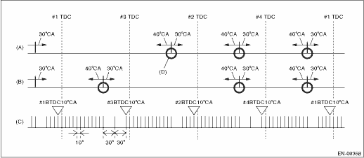
(A) | Camshaft signal (RH) | (B) | Camshaft signal (LH) | (C) | Crankshaft signal |
(D) | Camshaft position signal: When normal, there will be 3 camshaft position signals for every 2 crankshaft revolutions. |
3. EXECUTION CONDITION
Secondary Parameters | Execution condition |
Battery voltage | ≥ 8 V |
Secondary Parameters | Execution condition |
Battery voltage | ≥ 8 V |
Elapsed time after starting the engine | ≥ 200 ms |
4. GENERAL DRIVING CYCLE
Always perform the diagnosis continuously.
5. DIAGNOSTIC METHOD
Diagnosis 1
Judge as NG when no input of camshaft position sensor signal in TDC remains for 10 time(s).
Malfunction Criteria | Threshold Value |
Number of intake camshaft position sensor pulses during cranking | = 0 |
Time Needed for Diagnosis: TDC ? 10 time(s)
Diagnosis 2
If the duration of time while the following conditions are met is longer than the time indicated, judge as NG.
Malfunction Criteria | Threshold Value |
Number of intake camshaft position sensor pulses during 0.5 crankshaft rev. | = 0 |
Time Needed for Diagnosis: 3000 ms
Malfunction Indicator Light Illumination: Illuminates as soon as a malfunction occurs.
 Dtc p0336 crankshaft position sensor "a" circuit range/performance
ENGINE (DIAGNOSTICS)(H4DO) > Diagnostic Procedure with Diagnostic Trouble Code (DTC)DTC P0336 CRANKSHAFT POSITION SENSOR "A" CIRCUIT RANGE/PERFORMANCEDTC detecting condition:Detected when ...
 Dtc p0341 camshaft position sensor "a" circuit range/performance bank 1 or single sensor
ENGINE (DIAGNOSTICS)(H4DO) > Diagnostic Procedure with Diagnostic Trouble Code (DTC)DTC P0341 CAMSHAFT POSITION SENSOR "A" CIRCUIT RANGE/PERFORMANCE BANK 1 OR SINGLE SENSORNOTE:For the di ...
Other materials:
Inspection
HVAC SYSTEM (HEATER, VENTILATOR AND A/C) > Blower Resistor (Manual A/C Model)INSPECTION1. Check the resistance between resistor terminals.Preparation tool:Circuit testerTerminal No.StandardConnection diagram4 — 3Approx. 0.43 ?4 — 2Approx. 1.03 ?4 — 1Approx. 3 ?2. Replace the resistor if the ...
Access key
Access key (main)
Access key (sub)
Key number plate
The vehicle has two access keys and a
key number plate. For details about the
key number plate, refer to "Key number
plate" 2-3.
A mechanical key is attached to each
access key. The mechanical key is used
for the following opera ...
Dtc p0118 engine coolant temperature sensor 1 circuit high
ENGINE (DIAGNOSTICS)(H4DO) > Diagnostic Procedure with Diagnostic Trouble Code (DTC)DTC P0118 ENGINE COOLANT TEMPERATURE SENSOR 1 CIRCUIT HIGHDTC detecting condition:Immediately at fault recognitionTrouble symptom:• Hard to start• Improper idling• Poor driving performanceCAUTION ...
