Subaru Crosstrek Service Manual: Installation
CONTINUOUSLY VARIABLE TRANSMISSION(TR580) > Reverse Brake Assembly
INSTALLATION
1. Select a washer. Forward Clutch Assembly > ADJUSTMENT">
2. Install the selected washer to the reverse brake housing.
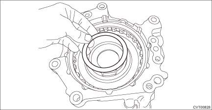
3. Install the thrust bearing to the reverse brake housing.
NOTE:
Face the temper color surface to the reverse brake side.
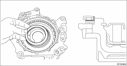
4. Remove the internal gear from the forward clutch assembly, and install it to the reverse brake housing.
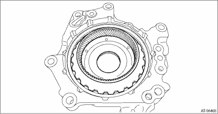
5. Install the O-rings.
NOTE:
• Install a new O-ring.
• Apply CVTF to the O-rings.
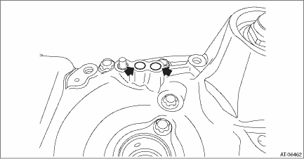
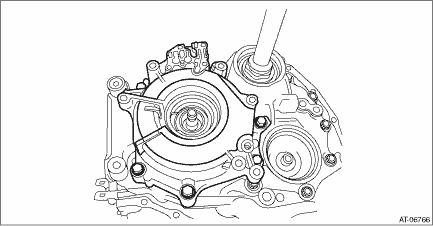
6. Install the reverse brake assembly and internal gear as a unit to the drive pinion retainer.
NOTE:
Slowly rotate the input shaft by hand to engage the internal gear and pinion gear of planetary carrier.
Tightening torque:
37 N·m (3.8 kgf-m, 27.3 ft-lb)
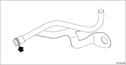
7. Install the O-ring to the lubrication pipe.
NOTE:
• Install a new O-ring.
• Apply CVTF to the O-rings.
8. Install the lubrication pipe and oil guide.
Tightening torque:
16 N·m (1.6 kgf-m, 11.8 ft-lb)
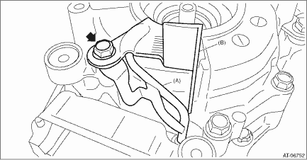
(A) | Lubrication pipe |
(B) | Oil guide |
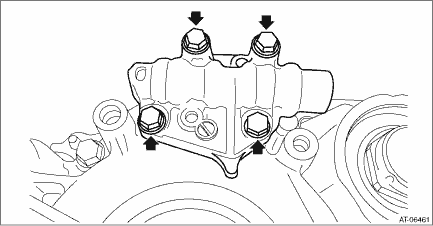
9. Install the manual valve assembly and separator plate.
Tightening torque:
9 N·m (0.9 kgf-m, 6.6 ft-lb)
10. Install the primary pulley, secondary pulley and variator chain. Primary Pulley and Secondary Pulley > INSTALLATION">
11. Select shims for pulley alignment. Primary Pulley and Secondary Pulley > ADJUSTMENT">
12. Install the reduction drive gear. Reduction Drive Gear > INSTALLATION">
13. Install the transmission case. Transmission Case > INSTALLATION">
14. Install the transmission control device. Transmission Control Device > INSTALLATION">
15. Install the oil strainer and oil pan. Oil Pan and Strainer > INSTALLATION">
16. Install the reduction driven gear assembly. Reduction Driven Gear > INSTALLATION">
17. Install the transfer driven gear assembly. Transfer Driven Gear > INSTALLATION">
18. Install the transfer clutch assembly. Transfer Clutch > INSTALLATION">
19. Install the parking pawl. Parking Pawl > INSTALLATION">
20. Install the extension case. Extension Case > INSTALLATION">
21. Install the inhibitor switch. Inhibitor Switch > INSTALLATION">
22. Install the secondary speed sensor. Secondary Speed Sensor > INSTALLATION">
23. Install the primary speed sensor. Primary Speed Sensor > INSTALLATION">
24. Install the turbine speed sensor. Turbine Speed Sensor > INSTALLATION">
25. Install the transmission harness. Transmission Harness > INSTALLATION">
26. Install the control valve body. Control Valve Body > INSTALLATION">
27. Install the air breather hose. Air Breather Hose > INSTALLATION">
28. Install the transmission assembly to the vehicle. Automatic Transmission Assembly > INSTALLATION">
 Inspection
CONTINUOUSLY VARIABLE TRANSMISSION(TR580) > Reverse Brake AssemblyINSPECTION• Inspect the drive plate facing for wear and damage.• Check the driven plate for discoloration (burnt color) ...
Other materials:
Dtc p219a bank 1 air-fuel ratio imbalance
ENGINE (DIAGNOSTICS)(H4DO) > Diagnostic Procedure with Diagnostic Trouble Code (DTC)DTC P219A BANK 1 AIR-FUEL RATIO IMBALANCEDTC detecting condition:Detected when two consecutive driving cycles with fault occur.Trouble symptom:• Engine stall• Improper idlingCAUTION:After servicing or ...
Installation
CLUTCH SYSTEM > FlywheelINSTALLATION1. Press in a new pilot bearing to the position where it is flush with the flywheel surface or up to 0.4 mm (0.016 in) deeper than that.CAUTION:Do not press the bearing inner ring.(A)Pilot bearing2. Temporarily tighten the crankshaft position sensor plate and f ...
Component
EMISSION CONTROL (AUX. EMISSION CONTROL DEVICES)(H4DO) > General DescriptionCOMPONENT1. CANISTER, LEAK CHECK VALVE ASSEMBLY AND DRAIN SEPARATORFor structures of the canister, leak check valve assembly and drain separator, refer to “FU (H4DO)”. General Description > COMPONENT" ...

