Subaru Crosstrek Service Manual: Installation
CONTINUOUSLY VARIABLE TRANSMISSION(TR580) > Front Differential Assembly
INSTALLATION
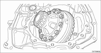
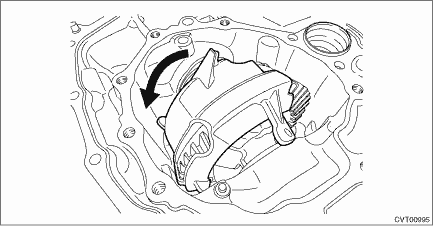
1. Install the front differential assembly to the converter case.
NOTE:
Be careful not to damage the inside of the case (especially the mounting surface of the differential side retainers).

2. Install the bearing outer race.
3. Temporarily install the differential side retainers using ST.
| ST 18658AA020 | WRENCH COMPL RETAINER |

4. Adjust the backlash of the front differential. Front Differential Assembly > ADJUSTMENT">
5. Inspect and adjust the tooth contact. Drive Pinion Shaft Assembly > ADJUSTMENT">
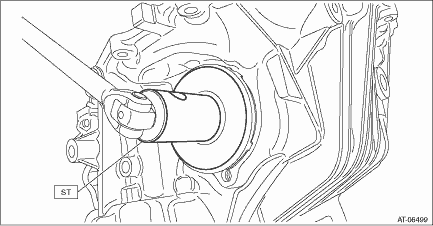
6. Using the ST, loosen the differential side retainer until the mounting groove of the O-ring appears, and then install the O-ring.
NOTE:
• When loosening the differential side retainer, record the number of the turns made.
• Perform this for both left and right differential side retainers.
• Use new O-rings.
• Apply the differential gear oil to O-ring.
| ST 18658AA020 | WRENCH COMPL RETAINER |
7. Using the ST, tighten the retainer to the position before it is loosened.
| ST 18658AA020 | WRENCH COMPL RETAINER |
8. Install the oil seal to the differential side retainer. Differential Side Retainer Oil Seal">
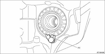
9. Install the lock plate.
Tightening torque:
25 N·m (2.5 kgf-m, 18.4 ft-lb)

(A) | Lock plate |
10. Install the oil baffle.

11. Install the drive pinion shaft assembly. Drive Pinion Shaft Assembly > INSTALLATION">
12. Install the forward clutch assembly. Forward Clutch Assembly > INSTALLATION">
13. Install the reverse brake assembly. Reverse Brake Assembly > INSTALLATION">
14. Install the primary pulley, secondary pulley and variator chain. Primary Pulley and Secondary Pulley > INSTALLATION">
15. Install the reduction drive gear. Reduction Drive Gear > INSTALLATION">
16. Install the transmission case. Transmission Case > INSTALLATION">
17. Install the oil strainer and oil pan. Oil Pan and Strainer > INSTALLATION">
18. Install the transmission control device. Transmission Control Device > INSTALLATION">
19. Install the reduction driven gear assembly. Reduction Driven Gear > INSTALLATION">
20. Install the transfer driven gear assembly. Transfer Driven Gear > INSTALLATION">
21. Install the transfer clutch assembly. Transfer Clutch > INSTALLATION">
22. Install the parking pawl. Parking Pawl > INSTALLATION">
23. Install the extension case. Extension Case > INSTALLATION">
24. Install the inhibitor switch. Inhibitor Switch > INSTALLATION">
25. Install the secondary speed sensor. Secondary Speed Sensor > INSTALLATION">
26. Install the primary speed sensor. Primary Speed Sensor > INSTALLATION">
27. Install the turbine speed sensor. Turbine Speed Sensor > INSTALLATION">
28. Install the transmission harness. Transmission Harness > INSTALLATION">
29. Install the control valve body. Control Valve Body > INSTALLATION">
30. Install the air breather hose. Air Breather Hose > INSTALLATION">
31. Install the transmission assembly to the vehicle. Automatic Transmission Assembly > INSTALLATION">
 Inspection
CONTINUOUSLY VARIABLE TRANSMISSION(TR580) > Front Differential AssemblyINSPECTION• Check each component for scratches, damage or other faults.• Using the ST, check the backlash of pinio ...
Other materials:
Disassembly
INSTRUMENTATION/DRIVER INFO > Combination MeterDISASSEMBLYCAUTION:• Use gloves to avoid damage and getting fingerprints on the glass surface and meter surfaces.• Be careful not to apply excessive force to the trip knob.• Be sure not to touch the meter indicator needle.• Be ...
Inspection
ENGINE (DIAGNOSTICS)(H4DO) > General DescriptionINSPECTIONBefore performing diagnostics, check the following item which might affect engine problems.1. BATTERY1. Check the battery. Battery > INSPECTION">2. Check the condition of the main and other fuses, and harnesses and connectors. ...
Installation
HVAC SYSTEM (HEATER, VENTILATOR AND A/C) > Heater CoreINSTALLATIONCAUTION:• Replace O-rings and clamps with new parts and install securely.• Before handling the airbag system components, refer to “CAUTION” of “General Description” in “AIRBAG SYSTEM” ...

