Subaru Crosstrek Service Manual: Installation
CLUTCH SYSTEM > Master Cylinder
INSTALLATION
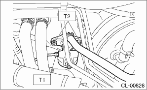
1. Install the master cylinder to the body, and connect the clutch pipe and the tank hose.
Tightening torque:
T1: 15 N·m (1.5 kgf-m, 11.1 ft-lb)
T2: 18 N·m (1.8 kgf-m, 13.3 ft-lb)
2. Connect the push rod of the master cylinder, and install the clevis pin and snap pin.
CAUTION:
Always use a new clevis pin.
NOTE:
Apply grease to the clevis pin.
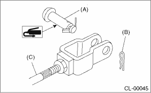
(A) | Clevis pin |
(B) | Snap pin |
(C) | Push rod |
3. Install the knee airbag module. Knee Airbag Module > INSTALLATION">
4. Fill the recommended brake fluid. Clutch Fluid">
5. After bleeding air from the clutch system, ensure that the clutch operates properly. Clutch Fluid Air Bleeding">
6. Install the cover assembly - instrument panel LWR driver. Instrument Panel Lower Cover > INSTALLATION">
7. Install the air intake boot. Air Intake Boot > INSTALLATION">
8. Connect the battery ground terminal.
 Inspection
CLUTCH SYSTEM > Master CylinderINSPECTIONIf any damage, deformation, wear, swelling, rust or other faults are found on the cylinder, piston, push rod, nipple, return spring, bleeder screw, seat or ...

Other materials:
Self-check screen
When the ignition switch is turned to the
"ON" position, the vehicle self-check will
be performed. The screens corresponding
to the following items will appear one after
another for several seconds each.
Engine oil: Checks the interval of engine
oil replacement.
Oil filter: Checks th ...
Most common causes of corrosion
The most common causes of corrosion
are:
The accumulation of moisture retaining
dirt and debris in body panel sections,
cavities, and other areas.
Damage to paint and other protective
coatings caused by gravel and stone
chips or minor accidents.
Corrosion is accelerated on the vehic ...
Inspection
STARTING/CHARGING SYSTEMS(H4DO) > BatteryINSPECTIONWARNING:• As batteries produce flammable gases, be careful not to bring an open flame close to the batteries.• Ventilate sufficiently when using or charging battery in enclosed space.• Electrolyte is corrosive acid, and has toxi ...
