Subaru Crosstrek Service Manual: Installation
CLUTCH SYSTEM > Clutch Disc and Cover
INSTALLATION
1. Insert the ST into the clutch disc and the ST end into pilot bearing to install the clutch disc.
NOTE:
When installing the clutch disc, be careful to attach in the correct direction.
| ST 499747100 | CLUTCH DISC GUIDE |
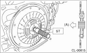
(A) | Flywheel side |
2. Install the clutch cover and tighten the bolts to the specified torque.
NOTE:
• When installing the clutch cover, position the clutch cover so that the spacing between the unbalance marks (paint mark) on the flywheel and clutch cover is 120° or more apart. (The unbalance mark indicates the direction of residual unbalance.)
• Temporarily tighten the bolts by hand. Each bolt should be tightened to the specified torque in a crisscross order.
Tightening torque:
16 N·m (1.6 kgf-m, 11.8 ft-lb)
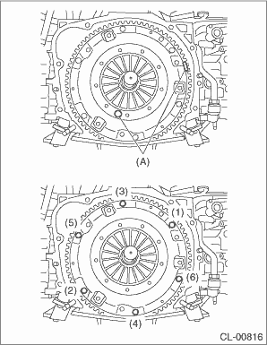
(A) | Unbalance mark (paint) |
3. Remove the ST.
| ST 499747100 | CLUTCH DISC GUIDE |
4. Install the transmission assembly. Manual Transmission Assembly > INSTALLATION">
 Removal
CLUTCH SYSTEM > Clutch Disc and CoverREMOVAL1. Remove the transmission assembly from the vehicle. Manual Transmission Assembly > REMOVAL">2. Attach the ST on the flywheel.ST 499747100 ...
 Clutch fluid
...
Other materials:
Electronic Brake Force Distribution (EBD) system
The EBD system maximizes the effectiveness
of the brakes by allowing the rear
brakes to supply a greater proportion of
the braking force. It functions by adjusting
the distribution of braking force to the rear
wheels in accordance with the vehicle's
loading condition and speed.
The EBD syst ...
ABS (Anti-lock Brake System)
The ABS system in the Subaru Ascent is engineered to prevent wheel lock-up during
sudden or emergency braking, especially on slippery or uneven road surfaces. By
maintaining wheel rotation, the system allows the driver to retain steering control
and directional stability, reducing the risk of ...
Check list for interview Check
POWER ASSISTED SYSTEM (POWER STEERING) (DIAGNOSTICS) > Check List for InterviewCHECKCheck the following items regarding condition of the vehicle.1. TROUBLE STATUSPhenomenon of the vehicle Steering is heavy Steering is not smooth Steering is unstable (wondering) Steering does not return to center ...
