Subaru Crosstrek Service Manual: Installation
BRAKE > Stop Light Switch
INSTALLATION
1. BULB TYPE
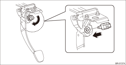
1. Install the stop light switch.
CAUTION:
• Turn the stop light switch clockwise when installing so that it can return backward by approximately 1 mm (0.04 in) and clearance is automatically adjusted.
• If it is hard to turn the switch, reduce the switch pushing force and turn it again.
(1) While pulling up the brake pedal toward you, contact the stop light switch to the stopper and temporarily install it by rotating it clockwise.
(2) Adjust the stop light switch position, and install it. Stop Light Switch > ADJUSTMENT">
(3) Install the stop light switch connector.
2. Install the cover assembly - instrument panel LWR driver.
3. Connect the battery ground terminal.
4. Check that the brake light operate properly.
5. Check the stop light switch operation.
(1) Turn the ignition switch to OFF and connect the Subaru Select Monitor.
(2) Start the engine and warm it up to a sufficient temperature.
NOTE:
Perform the following operations with the engine running.
(3) Display the data of «Brake Switch» and «Pressure Sensor Output» by following the Subaru Select Monitor display screen.
(4) Check that the stop light switch is ON with the brake pedal not depressed.
(5) Quickly depress the brake pedal 5 times.
(6) Slowly release the brake pedal depressed at the fifth time and check that the master cylinder pressure is within the standard value when the stop light switch changes from ON to OFF.
Specification:
Less than 1 Mpa (10 bar)
2. LED TYPE
1. Adjust the stop light switch position, and then secure the stop light switch by turning it clockwise. Stop Light Switch > ADJUSTMENT">
2. Install each part in the reverse order of removal.
3. Check the stop light switch operation.
 Inspection
BRAKE > Stop Light SwitchINSPECTION1. CLEARANCE CHECKNOTE:Check for clearance is applied only to LED model.1. Measure the clearance between the end of the stop light switch and the stopper.Specific ...
 Air bleeding Procedure
BRAKE > Air BleedingPROCEDURECAUTION:• Do not let brake fluid come into contact with the painted surface of the vehicle body. Wash away with water immediately and wipe off if it is spilled by ...
Other materials:
Removal
EXTERIOR/INTERIOR TRIM > Rear BumperREMOVAL1. CROSSTREK MODEL1. Disconnect the ground cable from battery. NOTE">2. Remove the light assembly - rear combination.CAUTION:Be careful not to damage the clips.(1) Release the bolts and clips, then pull out the light assembly - rear combination ...
Removal
EXHAUST(H4DO) > Center Exhaust PipeREMOVALCAUTION:Vehicle components are extremely hot after driving. Be wary of receiving burns from heated parts.1. Turn the ignition switch to OFF.2. Lift up the vehicle.3. Remove the bolts, springs, and nuts securing the rear exhaust pipe to the center exhaust ...
Check engine warning light/Malfunction indicator light
CAUTION
If the CHECK ENGINE light illuminates
while you are driving, have
your vehicle checked/repaired by
your SUBARU dealer as soon as
possible. Continued vehicle operation
without having the emission
control system checked and repaired
as necessary could cause
serious damage, which may n ...
