Subaru Crosstrek Service Manual: Inspection
BRAKE > Stop Light Switch
INSPECTION
1. CLEARANCE CHECK
NOTE:
Check for clearance is applied only to LED model.
1. Measure the clearance between the end of the stop light switch and the stopper.
Specification:
Clearance (A) of the stop light switch: 1 mm — 2 mm (0.04 in — 0.08 in)
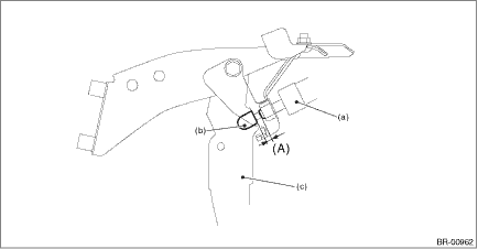
(a) | Stop light switch | (b) | Stopper | (c) | Brake pedal |
2. Adjust the position of the stop light switch if the inspection result is not within the standard value. Stop Light Switch > ADJUSTMENT">
2. CHECK RESISTANCE
1. Disconnect the stop light switch connector.
2. Measure the resistance between stop light switch terminals.
Preparation tool:
Circuit tester
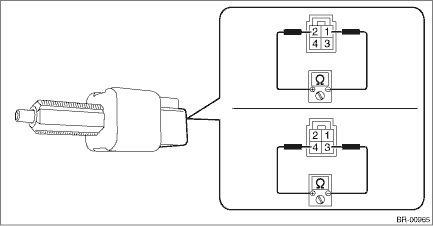
• Bulb type
Terminal No. | Inspection conditions | Standard |
1 — 2 | When brake pedal is depressed | 1 M? or more |
When brake pedal is released | Less than 1 ? | |
3 — 4 | When brake pedal is depressed | Less than 1 ? |
When brake pedal is released | 1 M? or more |
• LED type
Terminal No. | Inspection conditions | Standard |
1 — 2 | When brake pedal is depressed | Less than 1 ? |
When brake pedal is released | 1 M? or more | |
3 — 4 | When brake pedal is depressed | 1 M? or more |
When brake pedal is released | Less than 1 ? |
3. Replace the stop light switch if the inspection result is not within the standard value.
 Removal
BRAKE > Stop Light SwitchREMOVALCAUTION:Before handling the airbag system components, always refer to “CAUTION” of “General Description” in “AIRBAG SYSTEM”. Gen ...
 Installation
BRAKE > Stop Light SwitchINSTALLATION1. BULB TYPE1. Install the stop light switch.CAUTION:• Turn the stop light switch clockwise when installing so that it can return backward by approximatel ...
Other materials:
General diagnostic table Inspection
CONTROL SYSTEMS > General Diagnostic TableINSPECTIONSymptomsPossible causeCorrective actionSelect leverStarter does not run.Adjust the select cable and inhibitor switch, or inspect the circuit.Back-up light does not illuminate.Adjust the select cable and inhibitor switch, or inspect the circuit.A ...
Check cruise indicator light and cruise set indicator light
CRUISE CONTROL SYSTEM (DIAGNOSTICS) > Diagnostics with PhenomenonCHECK CRUISE INDICATOR LIGHT AND CRUISE SET INDICATOR LIGHTTROUBLE SYMPTOM:Cruise control can be set, but the CRUISE indicator and SET indicator do not illuminate.STEPCHECKYESNO1.CHECK CRUISE INDICATOR LIGHT AND CRUISE SET INDICATOR ...
Gasoline for cleaner air
Your use of gasoline with detergent
additives will help prevent deposits from
forming in your engine and fuel system.
This helps keep your engine in tune and
your emission control system working
properly, and is a way of doing your part
for cleaner air. If you continuously use a
high qualit ...
