Subaru Crosstrek Service Manual: Inspection
SEATS > Seat Heater System
INSPECTION
1. WIRING DIAGRAM
Refer to “Seat Heater System” in the wiring diagram. Seat Heater System > WIRING DIAGRAM">
2. DIAGNOSTIC CHART
Symptoms | Repair order |
Seat heater does not operate. | 1. Check the fuse. Seat Heater System > INSPECTION"> |
2. Check the seat heater relay. Seat Heater System > INSPECTION"> | |
3. Check the seat heater system power supply and ground circuit. Seat Heater System > INSPECTION"> | |
4. Check the seat heater module. Seat Heater System > INSPECTION"> | |
5. Check the seat heater switch circuit. Seat Heater System > INSPECTION"> |
3. CHECK SEAT HEATER FUSE
Remove the seat heater fuse and inspect visually.
Is the fuse blown out?
• Yes > Replace the fuse.
• No > Check the power supply and ground circuits.
4. CHECK SEAT HEATER RELAY
1. Remove the seat heater relay from the relay holder.
2. Measure the resistance between seat heater relay terminals.
Preparation tool: Circuit tester
Terminal No. | Inspection conditions | Standard | Circuit |
36 — 37 | Always | 1 M? or more |
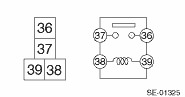
36 — 37
Apply battery voltage between terminals 38 — 39.
Less than 1 ?
3. Replace the seat heater relay if the inspection result is not within the standard.
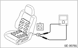
5. CHECK POWER SUPPLY AND GROUND CIRCUIT
1. Check power supply circuit
(1) Disconnect the harness connector of seat heater switch.
(2) Turn the ignition switch to ON.
(3) Measure the voltage between harness connector terminal and chassis ground.
Connector & terminal
(R43) No. 7 (+) — Chassis ground (−):
Is the voltage 12 V or more?
• Yes > Go to step 2.
• No > Check the harness between the seat heater switch and fuse.
2. Check ground circuit
Measure the resistance between harness connector terminal and chassis ground.
Connector & terminal
(R43) No. 2 — Chassis ground:
Is the resistance less than 10 ??
• Yes > Go to step 3.
• No > Repair the harness.
3. Check ground circuit
Measure the resistance between seat heater switch terminals.
Connector & terminal
(R43) No. 7 — (R43) No. 2:
Is the resistance less than 10 ??
• Yes > The power supply and ground circuits are normal.
• No > Replace the seat heater switch.
6. SEAT HEATER UNIT
1. Disconnect the seat heater unit connector, and check the continuity between terminals of connector.
Connector & terminal
HI
No. 1 — No. 3:
No. 3 — No. 4:
LOW
No. 1 — No. 4:
2. If no continuity exists, replace the seat heater module with a new part.
7. SEAT HEATER SWITCH
1. Inspect the continuity between the seat heater switch terminals.
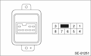
Connector & terminal
HI
No. 7 — No. 2:
No. 7 — No. 4:
No. 7 — No. 8:
LOW
No. 7 — No. 1:
No. 7 — No. 2:
No. 7 — No. 3:
2. If no continuity exists, replace the seat heater switch with a new part.

 Removal
SEATS > Seat Heater SystemREMOVAL1. SEAT HEATER UNIT1. Remove the front seats. Front Seat > REMOVAL">2. Remove the backrest cover of front seat and seat cushion cover. Front Seat > ...
Other materials:
Shock sensors (dealer option)
The shock sensors trigger the alarm
system when they sense impacts applied
to the vehicle and when any of their
electric wires are cut. The alarm system
causes the horn to sound and the hazard
warning flashers to flash for a short time
when the sensed impact is weak, but it
warns of a strong ...
Inspection
COOLING(H4DO) > ThermostatINSPECTION1. Check that the thermostat does not have deformation, cracks or damage.2. Check that the thermostat valve closes completely at an ambient temperature.3. Immerse the thermostat and a thermometer in water. Raise water temperature gradually, and check the temper ...
Fastening the seatbelt
WARNING
Never use a belt that is twisted or
reversed. In an accident, this can
increase the risk or severity of
injury.
Keep the lap belt as low as
possible on your hips. In a collision,
this spreads the force of the
lap belt over stronger hip bones
instead of across the weaker
...
