Subaru Crosstrek Service Manual: Inspection
HVAC SYSTEM (HEATER, VENTILATOR AND A/C) > Control Panel
INSPECTION
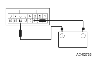
1. CHECK ILLUMINATION
1. Check the illumination operation when battery voltage is applied between the terminals of control panel.
• Manual A/C model
Terminal No. | Inspection conditions | Specification | Connection diagram |
14 (+) — 12 (−) | Connect battery to the terminals | Light ON |
• Auto A/C model
Terminal No. | Inspection conditions | Specification | Connection diagram |
37 (+) — 35 (−) | Connect battery to the terminals | Light ON |

2. If it does not operate normally, replace the heater control assembly.
2. BLOWER SWITCH (MANUAL A/C MODEL)
1. Measure the resistance between the control panel terminals.
Preparation tool:
Circuit tester
Terminal No. | Inspection conditions | Standard | Connection diagram |
— | OFF | — | — |
1 — 2, 4 | 1 (LO) | Less than 1 ? |
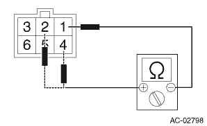
1 — 3, 4
2 (M1)
Less than 1 ?
1 — 4, 6
3 (M2)
Less than 1 ?
1 — 4, 5
4 (HI)
Less than 1 ?
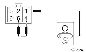
2. Replace the heater control assembly if the inspection result is not within the standard.
 Control panel
...
 Removal
HVAC SYSTEM (HEATER, VENTILATOR AND A/C) > Control PanelREMOVALCAUTION:Before handling the airbag system components, refer to “CAUTION” of “General Description” in “AI ...
Other materials:
Installation
INTAKE (INDUCTION)(H4DO) > Air Cleaner ElementINSTALLATIONInstall in the reverse order of removal.CAUTION:Be sure to use SUBARU genuine air cleaner element depending on the engine type when replacing the air cleaner elements. Using other air cleaner element may affect the engine performance.NOTE: ...
Dtc p0010 "a" camshaft position actuator control circuit/open bank 1
ENGINE (DIAGNOSTICS)(H4DO) > Diagnostic Procedure with Diagnostic Trouble Code (DTC)DTC P0010 "A" CAMSHAFT POSITION ACTUATOR CONTROL CIRCUIT/OPEN BANK 1DTC detecting condition:Immediately at fault recognitionTrouble symptom:Improper idlingCAUTION:After servicing or replacing faulty part ...
Dtc u0423 invalid data received from instrument panel cluster control module
Blind Spot Detection/Rear Cross Traffic Alert (DIAGNOSTICS) > Diagnostic Procedure with Diagnostic Trouble Code (DTC)DTC U0423 INVALID DATA RECEIVED FROM INSTRUMENT PANEL CLUSTER CONTROL MODULEReceived error data from combination meter.NOTE:Perform the diagnosis for LAN system. Basic Diagnostic ...
