Subaru Crosstrek Service Manual: Dtc p0010 "a" camshaft position actuator control circuit/open bank 1
ENGINE (DIAGNOSTICS)(H4DO) > Diagnostic Procedure with Diagnostic Trouble Code (DTC)
DTC P0010 "A" CAMSHAFT POSITION ACTUATOR CONTROL CIRCUIT/OPEN BANK 1
DTC detecting condition:
Immediately at fault recognition
Trouble symptom:
Improper idling
CAUTION:
After servicing or replacing faulty parts, perform Clear Memory Mode Clear Memory Mode > OPERATION"> , and Inspection Mode Inspection Mode > PROCEDURE">.
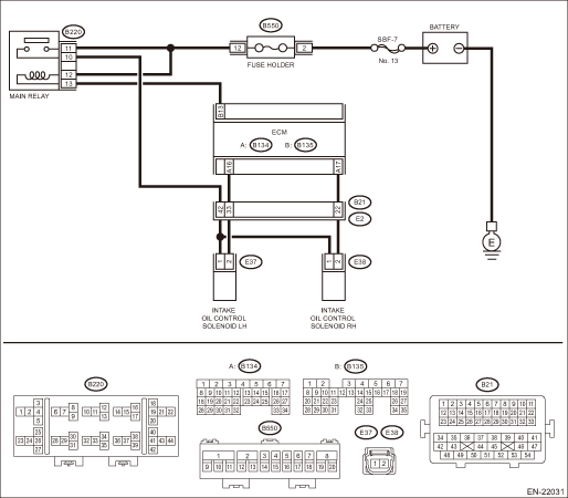
Wiring diagram:
Engine electrical system Power Supply Circuit">
| STEP | CHECK | YES | NO |
1.CHECK OUTPUT SIGNAL OF ECM.
1) Turn the ignition switch to ON.
2) Measure the voltage between ECM connector and chassis ground.
Connector & terminal
(B134) No. 17 (+) — Chassis ground (−):
Is the voltage 10 V or more?
Diagnostic Procedure with Diagnostic Trouble Code (DTC) > DTC P0010 "A" CAMSHAFT POSITION ACTUATOR CONTROL CIRCUIT/OPEN BANK 1">Go to Step 2.
Diagnostic Procedure with Diagnostic Trouble Code (DTC) > DTC P0010 "A" CAMSHAFT POSITION ACTUATOR CONTROL CIRCUIT/OPEN BANK 1">Go to Step 3.
2.CHECK FOR POOR CONTACT.
Check for poor contact of ECM connector.
Is there poor contact of ECM connector?
Repair the poor contact of ECM connector.
Even if DTC is detected, the circuit has returned to a normal condition at this time. Reproduce the failure, and then perform the diagnosis again.
NOTE:
In this case, temporary poor contact of connector, temporary open or short circuit of harness may be the cause.
3.CHECK POWER SUPPLY TO THE INTAKE OIL CONTROL SOLENOID RH.
Measure the voltage between intake oil control solenoid RH connector and engine ground.
Connector & terminal
(E38) No. 1 (+) — Engine ground (−):
Is the voltage 10 V or more?
Diagnostic Procedure with Diagnostic Trouble Code (DTC) > DTC P0010 "A" CAMSHAFT POSITION ACTUATOR CONTROL CIRCUIT/OPEN BANK 1">Go to Step 4.
Repair the power supply circuit.
4.CHECK HARNESS BETWEEN ECM AND INTAKE OIL CONTROL SOLENOID RH CONNECTOR.
1) Turn the ignition switch to OFF.
2) Disconnect the connector from ECM.
3) Disconnect the connector from the intake oil control solenoid RH.
4) Measure the resistance between intake oil control solenoid RH connector and engine ground.
Connector & terminal
(E38) No. 2 — Engine ground:
Is the resistance 1 M? or more?
Diagnostic Procedure with Diagnostic Trouble Code (DTC) > DTC P0010 "A" CAMSHAFT POSITION ACTUATOR CONTROL CIRCUIT/OPEN BANK 1">Go to Step 5.
Repair the short circuit to ground in harness between ECM connector and intake oil control solenoid RH connector.
5.CHECK HARNESS BETWEEN ECM AND INTAKE OIL CONTROL SOLENOID RH CONNECTOR.
Measure the resistance of harness between ECM connector and intake oil control solenoid RH.
Connector & terminal
(B134) No. 17 — (E38) No. 2:
Is the resistance less than 1 ??
Diagnostic Procedure with Diagnostic Trouble Code (DTC) > DTC P0010 "A" CAMSHAFT POSITION ACTUATOR CONTROL CIRCUIT/OPEN BANK 1">Go to Step 6.
Repair the harness and connector.
NOTE:
In this case, repair the following item:
• Open circuit in harness between ECM connector and intake oil control solenoid RH connector
• Poor contact of coupling connector
6.CHECK INTAKE OIL CONTROL SOLENOID RH.
Measure the resistance between intake oil control solenoid RH terminals.
Terminals
No. 1 — No. 2:
Is the resistance 6 — 12 ??
Repair the poor contact of intake oil control solenoid RH connector.
Replace the intake oil control solenoid RH. Oil Control Solenoid">
1. OUTLINE OF DIAGNOSIS
Detect open or short circuit of the oil control solenoid.
Judge as NG when the current is small even though the duty signal is large.
2. EXECUTION CONDITION
Secondary Parameters | Execution condition |
Battery voltage | ≥ 10.9 V |
Oil control solenoid control duty | ≥ 99.61 % |
3. GENERAL DRIVING CYCLE
Always perform the diagnosis continuously.
4. DIAGNOSTIC METHOD
If the duration of time while the following conditions are met is longer than the time indicated, judge as NG.
Malfunction Criteria | Threshold Value |
Oil control solenoid control present current | < 0.306 A |
Time Needed for Diagnosis: 2000 ms
Malfunction Indicator Light Illumination: Illuminates as soon as a malfunction occurs.
 Dtc p000d "b" camshaft position slow response bank 2
ENGINE (DIAGNOSTICS)(H4DO) > Diagnostic Procedure with Diagnostic Trouble Code (DTC)DTC P000D "B" CAMSHAFT POSITION SLOW RESPONSE BANK 2NOTE:For the diagnostic procedure, refer to DTC P00 ...
 Dtc p0011 "a" camshaft position - timing over-advanced or system performance bank 1
ENGINE (DIAGNOSTICS)(H4DO) > Diagnostic Procedure with Diagnostic Trouble Code (DTC)DTC P0011 "A" CAMSHAFT POSITION - TIMING OVER-ADVANCED OR SYSTEM PERFORMANCE BANK 1DTC detecting condit ...
Other materials:
Removal
WIPER AND WASHER SYSTEMS > Front Washer Nozzle and HoseREMOVAL1. NOZZLE - WINDSHIELD WASHER & HOSE1. Remove the arm assembly - windshield wiper. Front Wiper Arm > REMOVAL">2. Remove the cowl panel - side and the cowl panel assembly. Cowl Panel > REMOVAL">CAUTION:Before ...
Removal
HVAC SYSTEM (HEATER, VENTILATOR AND A/C) > Hose and PipeREMOVAL1. LOW-PRESSURE HOSE1. Using the refrigerant recovery system, discharge refrigerant. Refrigerant Recovery Procedure > PROCEDURE">2. Remove the air intake boot. Air Intake Boot > REMOVAL">CAUTION:Move aside the ...
Preparation tool
STARTING/CHARGING SYSTEMS(H4DO) > General DescriptionPREPARATION TOOL1. GENERAL TOOLTOOL NAMEREMARKSCircuit testerUsed for measuring resistance, voltage and current.NOTE:• For measuring standby current, prepare a circuit tester that can measure by 1 mA unit.• For measuring standby cur ...
