Subaru Crosstrek Service Manual: Inspection
GLASS/WINDOWS/MIRRORS > Front Regulator and Motor Assembly
INSPECTION
1. Disconnect the connector of the motor - front.
2. Check the motor operation when battery voltage is applied between terminals of the motor - front connector.
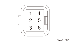
• LH side
Terminal No. | Inspection conditions | Standard |
4 (+) — 1 (−) | Apply battery voltage between terminals. | Increase |
1 (+) — 4 (−) | Apply battery voltage between terminals. | Decrease |
• RH side
Terminal No. | Inspection conditions | Standard |
3 (+) — 6 (−) | Apply battery voltage between terminals. | Increase |
6 (+) — 3 (−) | Apply battery voltage between terminals. | Decrease |
3. If it does not operate properly as a result of inspection, replace the regulator and motor assembly - front.

 Removal
GLASS/WINDOWS/MIRRORS > Front Regulator and Motor AssemblyREMOVAL1. Disconnect the ground cable from battery and wait for at least 60 seconds before starting work. NOTE">2. Remove the trim ...
Other materials:
Caution
SPEED CONTROL SYSTEMS(H4DO) > General DescriptionCAUTION• Prior to starting work, pay special attention to the following:1. Always wear work clothes, a work cap, and protective shoes. Additionally, wear a helmet, protective goggles, etc. if necessary.2. Protect the vehicle using a seat cove ...
Installation
CONTINUOUSLY VARIABLE TRANSMISSION(TR580) > Automatic Transmission AssemblyINSTALLATION1. Attach the ST to converter case.ST 498277200STOPPER SET2. When completely overhauling the transmission, refill CVTF through the transmission right side plug. Preparation for Overhaul">3. Replace ...
Dtc b28b7 ldp off switch
EyeSight (DIAGNOSTICS) > Diagnostic Procedure with Diagnostic Trouble Code (DTC)DTC B28B7 LDP OFF SWITCHDetected when lane departure warning OFF switch circuit is not installed, open-circuited, or is stuck to ON.DTC detecting condition:• Wiring of lane departure warning OFF switch is not co ...
