Subaru Crosstrek Service Manual: Inspection
ENTERTAINMENT > Switches and Harness
INSPECTION
1. SATELLITE SWITCH ASSEMBLY
1. Measure the resistance between connector terminals.
Preparation tool:
Circuit tester
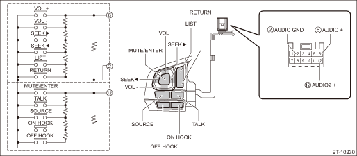
Terminal No. | Inspection conditions | Standard | |
6 — 2 | VOL (+) VOL (−) SEEK (›) SEEK (‹) LIST RETURN | A circuit is all OFF. | Approx. 100 k? |
VOL (+) | ON | Less than 1 ? | |
VOL (−) | ON | Approx. 50 ? | |
Preset CH UP/SEEK (›) | ON | Approx. 120 ? | |
Preset CH DOWN/SEEK (‹) | ON | Approx. 230 ? | |
LIST | ON | Approx. 430 ? | |
RETURN | ON | Approx. 1,000 ? | |
12 — 2 | MUTE/ENTER TALK SOURCE ON HOOK OFF HOOK | B circuit is all OFF. | Approx. 100 k? |
MUTE/ENTER | ON | Less than 1 ? | |
TALK | ON | Approx. 50 ? | |
SOURCE | ON | Approx. 120 ? | |
ON HOOK | ON | Approx. 230 ? | |
OFF HOOK | ON | Approx. 430 ? | |
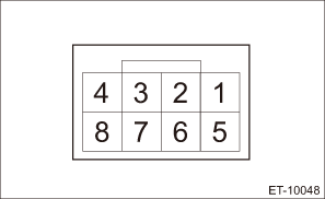
2. Apply battery voltage between the connector terminals to check lighting condition of illumination inside the switch.
Terminal No. | Inspection conditions | Specification |
10 (+) — 11 (−) | Apply battery voltage. | Light ON |
3. If the result of the measurement is not at the standard, replace the satellite switch assembly.
2. TELEMATICS BUTTON
1. Check the button.
(1) Measure the resistance between connector terminals.
Preparation tool:
Circuit tester
• SOS button
Terminal No. | Inspection conditions | Standard |
6 — 1 | OFF | Approx. 1.6 k? |
ON | Less than 1 ? |
• i-button
Terminal No. | Inspection conditions | Standard |
3 — 1 | OFF | Approx. 1.6 k? |
ON | Less than 1 ? |
(2) Apply battery voltage between the connector terminals to check lighting condition of illumination inside the switch.
Terminal No. | Inspection conditions | Specification |
8 (+) — 2 (−) | Apply battery voltage. | Light ON |
2. Check the indicator.
(1) Check the continuity between the connectors.
Terminal No. | Indicator | Specification |
4 — 1 | Green | Continuity exists |
7 — 1 | Red | Continuity exists |
3. Replace the spot map light or stereo camera cover assembly if the inspection result is not within the standard value.

 Removal
ENTERTAINMENT > Switches and HarnessREMOVAL1. SATELLITE SWITCH ASSEMBLYCAUTION:Before handling the airbag system components, refer to “CAUTION” of “General Description” in & ...
Other materials:
Suspension
SPECIFICATIONS > CrosstrekSUSPENSIONModel2.0 L DOHC non-turboFrontMacpherson strut type suspensionRearDouble-wishbone type suspension ...
Installation
HVAC SYSTEM (HEATER, VENTILATOR AND A/C) > Heater CoreINSTALLATIONCAUTION:• Replace O-rings and clamps with new parts and install securely.• Before handling the airbag system components, refer to “CAUTION” of “General Description” in “AIRBAG SYSTEM” ...
Dtc p0852 park/neutral switch input circuit high
ENGINE (DIAGNOSTICS)(H4DO) > Diagnostic Procedure with Diagnostic Trouble Code (DTC)DTC P0852 PARK/NEUTRAL SWITCH INPUT CIRCUIT HIGH1. AT MODELDTC detecting condition:Detected when two consecutive driving cycles with fault occur.Trouble symptom:Improper idlingCAUTION:After servicing or replacing ...
