Subaru Crosstrek Service Manual: General scan tool Operation
ENGINE (DIAGNOSTICS)(H4DO) > General Scan Tool
OPERATION
1. HOW TO USE GENERAL SCAN TOOL
1. Prepare a scan tool (general scan tool) required by SAE J1978.
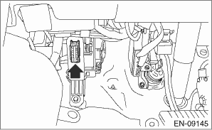
2. Connect the general scan tool to data link connector located in the lower portion of the instrument panel (on the driver’s side).
3. Using the general scan tool, call up each data. General scan tool functions consist of:
(1) MODE $01: Current powertrain diagnostic data
(2) MODE $02: Powertrain freeze frame data
(3) MODE $03: Emission-related powertrain DTC
(4) MODE $04: Clear/Reset emission-related diagnostic information
(5) MODE $06: Request on-board monitoring test results for intermittently monitored systems
(6) MODE $07: Initial emission-related powertrain DTC
(7) MODE $08: Request control for on-board system, test, and component
(8) MODE $09: Request vehicle information
4. Read out the data according to repair procedures. (For detailed operation procedures, refer to the general scan tool operation manual.)
NOTE:
For details concerning DTC, refer to “List of Diagnostic Trouble Code (DTC)”. List of Diagnostic Trouble Code (DTC)">
2. MODE $01: (CURRENT POWERTRAIN DIAGNOSTIC DATA)
Refer to data denoting the current operating condition of analog input/output, digital input/output or the powertrain system.
A list of the support data and PID (Parameter Identification) codes are shown in the following table.
PID | Data | Unit of measure |
$01 | Number of emission-related powertrain DTC, and malfunction indicator light status and diagnosis support information | — |
$03 | Fuel system control status | — |
$04 | Calculated engine load value | % |
$05 | Engine coolant temperature | °C |
$06 | Short term fuel trim | % |
$07 | Long term fuel trim | % |
$0B | Intake manifold absolute pressure | kPa |
$0C | Engine speed | rpm |
$0D | Vehicle speed | MPH |
$0E | Ignition timing advance | ° |
$0F | Intake air temperature | °C |
$10 | Intake air amount | g/s |
$11 | Throttle valve opening angle | % |
$13 | Air fuel ratio sensor | — |
$15 | Oxygen sensor output voltage and short term fuel trim associated with oxygen sensor (bank 1 sensor 2) | V and % |
$1C | Supporting OBD system | — |
$1F | Elapsed time after starting the engine | sec |
$21 | Travel distance after the malfunction indicator light illuminates | miles |
$24 | A/F value and A/F sensor output voltage (bank 1 sensor 1) | — and V |
$2C | Target EGR | % |
$2D | EGR deviation | % |
$2E | Evaporative purge | % |
$2F | Fuel level | % |
$30 | Number of warm ups after DTC clear | time |
$31 | Travel distance after DTC clear | miles |
$33 | Barometric pressure | kPa |
$34 | A/F value and A/F sensor current (bank 1 sensor 1) | — and mA |
$3C | Catalyst temperature #1 | °C |
$41 | Diagnostic monitor of each drive cycle | — |
$42 | ECM power voltage | V |
$43 | Absolute load | % |
$44 | A/F target lambda | — |
$45 | Relative throttle opening angle | % |
$46 | Ambient temperature | °C |
$47 | Absolute throttle opening angle 2 | % |
$49 | Absolute accelerator opening angle 1 | % |
$4A | Absolute accelerator opening angle 2 | % |
$4C | Target throttle opening angle | % |
$4D | Engine operating time while malfunction indicator lit | min |
$4E | Elapsed time after DTC clear | min |
$51 | Fuel used | — |
$53 | Evaporative Leak Check Module pressure | — |
$56 | Learning value of sub feedback compensation level | — |
$5A | Relative accelerator opening angle | % |
$5C | Engine oil temperature | °C |
$65 | Neutral status | — |
NOTE:
Refer to general scan tool manufacturer’s operation manual to access current powertrain diagnostic data (MODE $01).
3. MODE $02 (POWERTRAIN FREEZE FRAME DATA)
Refer to data denoting the operating condition when trouble is detected by on-board diagnosis system.
A list of the support data and PID (Parameter Identification) codes are shown in the following table.
PID | Data | Unit of measure |
$02 | DTC that caused freeze frame data to be stored | — |
$03 | Fuel system control status | — |
$04 | Calculated engine load value | % |
$05 | Engine coolant temperature | °C |
$06 | Short term fuel trim (bank 1 sensor 1) | % |
$07 | Long term fuel trim (bank 1 sensor 1) | % |
$0B | Intake manifold absolute pressure | kPa |
$0C | Engine speed | rpm |
$0D | Vehicle speed | MPH |
$0E | Ignition timing advance | ° |
$0F | Intake air temperature | °C |
$10 | Intake air amount | g/s |
$11 | Throttle valve opening angle | % |
$13 | Air fuel ratio sensor | — |
$15 | Oxygen sensor output voltage and short term fuel trim associated with oxygen sensor (bank 1 sensor 2) | V and % |
$1C | Supporting OBD system | — |
$1F | Elapsed time after starting the engine | sec |
$24 | A/F value and A/F sensor output voltage | — and V |
$2C | Target EGR | % |
$2D | EGR deviation | % |
$2E | Evaporative purge | % |
$2F | Fuel level | % |
$33 | Barometric pressure | kPa |
$34 | A/F value and A/F sensor output current | — and mA |
$3C | Catalyst temperature | °C |
$42 | ECM power voltage | V |
$43 | Absolute load | % |
$44 | A/F target lambda | — |
$45 | Relative throttle opening angle | % |
$46 | Ambient temperature | °C |
$47 | Absolute throttle opening angle 2 | % |
$49 | Absolute accelerator opening angle 1 | % |
$4A | Absolute accelerator opening angle 2 | % |
$4C | Target throttle opening angle | % |
$51 | Fuel used | — |
$5C | Engine oil temperature | °C |
$65 | Neutral status | — |
NOTE:
Refer to general scan tool manufacturer’s instruction manual to access freeze frame data (MODE $02).
4. MODE $03 (EMISSION-RELATED POWERTRAIN DTC)
Refer to “List of Diagnostic Trouble Code (DTC)” for information about data denoting emission-related powertrain DTC. List of Diagnostic Trouble Code (DTC)">
5. MODE $04 (CLEAR/RESET EMISSION-RELATED DIAGNOSTIC INFORMATION)
Refer to the mode used to clear or reset emission-related diagnostic information.
NOTE:
Refer to general scan tool manufacturer’s instruction manual to clear the emission-related diagnostic information (MODE $04).
6. MODE $06 (REQUEST ON-BOARD MONITORING TEST RESULTS FOR INTERMITTENTLY MONITORED SYSTEMS)
Refer to diagnostic value of troubleshooting and data of test limit indicated on the support data bit sequence table. A list of the support data is shown in the following table.
NOTE:
Some items are not displayed according to the specifications.
OBDMID | TID | SID | Diagnostic item |
$01 | $84 | $1E | A/F sensor range failure (Bank 1 Sensor 1) |
$85 | $1E | ||
$86 | $20 | A/F sensor response failure (Bank 1 Sensor 1) | |
$91 | $20 | ||
$92 | $10 | ||
$A3 | $20 | ||
$A4 | $10 | ||
$AC | $10 | ||
$AD | $10 | ||
$AE | $10 | ||
$AF | $10 | ||
$CD | $20 | ||
$CF | $20 | ||
$DF | $10 | ||
$02 | $07 | $0B | Oxygen sensor drop failure (Bank 1 Sensor 2) |
$08 | $0B | ||
$A5 | $FE | ||
$05 | $10 | Oxygen sensor response failure (Bank 1 Sensor 2) | |
$D1 | $10 | Oxygen sensor delay failure (Bank 1 Sensor 2) | |
$D2 | $01 | ||
$21 | $89 | $20 | Catalyst deterioration diagnosis (Bank 1) |
$31 | $8A | $FD | EGR system diagnosis |
$35 | $8B | $9D | VVT monitor (Bank 1) |
$8C | $9D | ||
$8D | $9D | ||
$8E | $9D | ||
$D3 | $9D | ||
$D5 | $9D | ||
$D6 | $9D | ||
$36 | $8B | $9D | VVT monitor (Bank 2) |
$8C | $9D | ||
$8D | $9D | ||
$8E | $9D | ||
$D3 | $9D | ||
$D5 | $9D | ||
$D6 | $9D | ||
$3C | $C1 | $FE | Evaporative emission control system (0.02 inch leak) |
$C2 | $FE | ||
$C3 | $FE | ||
$C4 | $FE | ||
$C5 | $FE | ||
$C6 | $35 | ||
$C7 | $FE | ||
$C8 | $FE | ||
$C9 | $FE | ||
$CA | $FE | ||
$3D | $E2 | $FE | Evaporative Leak Check Module Purge Flow |
$41 | $9B | $14 | A/F sensor heater characteristics failure (Bank 1 Sensor 1) |
$42 | $A2 | $24 | Oxygen sensor heater characteristics failure (Bank 1 Sensor 2) |
$A1 | $0B | $24 | Misfire monitoring (all cylinders) |
$0C | $24 | ||
$A2 | $0B | $24 | Misfire monitoring (#1 cylinder) |
$0C | $24 | ||
$A3 | $0B | $24 | Misfire monitoring (#2 cylinder) |
$0C | $24 | ||
$A4 | $0B | $24 | Misfire monitoring (#3 cylinder) |
$0C | $24 | ||
$A5 | $0B | $24 | Misfire monitoring (#4 cylinder) |
$0C | $24 |
7. MODE $07 (INITIAL EMISSION-RELATED POWERTRAIN DTC)
Refer to the data of DTC (pending code) for troubleshooting result about emission in the first time.
8. MODE $09
Perform “Active Test” of the on-board system.
9. MODE $09 (REQUEST VEHICLE INFORMATION)
Refer to the data of the vehicle specification.
 General diagnostic table Inspection
ENGINE (DIAGNOSTICS)(H4DO) > General Diagnostic TableINSPECTION1. ENGINENOTE:Malfunction of parts other than those listed is also possible. Engine Trouble in General">SymptomsFaulty parts1 ...
 Inspection mode Procedure
ENGINE (DIAGNOSTICS)(H4DO) > Inspection ModePROCEDUREPerform the diagnosis shown in the following DTC table.When performing the diagnosis not listed in “List of Diagnostic Trouble Code (DTC)& ...
Other materials:
Wiring diagram
ENTERTAINMENT > Audio SystemWIRING DIAGRAM1. AUDIORefer to “Audio System” in the wiring diagram.• 6.2 inch display: Audio System > WIRING DIAGRAM">• 7 inch display (model without telematics): Audio System > WIRING DIAGRAM">• 7 inch display (mo ...
Using the phone switch/microphone
Steering switch
By pressing the steering switch, a call can
be received or ended without taking your
hands off the steering wheel.
Volume control switch
Off hook switch
On hook switch
Microphone
The microphone is used when talking on
the phone.
Type A
Type B
How ...
Tongue load
Tongue load
Ensure that the trailer tongue load is from
8 to 11 percent of the total trailer weight
and does not exceed the maximum value
of 200 lbs (90 kg).
Jack
Bathroom scale
The tongue load can be weighed with a
bathroom scale as shown in the illustration
above. When weighing ...
