Subaru Crosstrek Service Manual: Inspection mode Procedure
ENGINE (DIAGNOSTICS)(H4DO) > Inspection Mode
PROCEDURE
Perform the diagnosis shown in the following DTC table.
When performing the diagnosis not listed in “List of Diagnostic Trouble Code (DTC)”, refer to the item on the drive cycle. Drive Cycle">
DTC | Item | Condition |
B1570 | ANTENNA | — |
B1571 | REFERENCE CODE INCOMPATIBILITY (IMMOBILIZER CM TO ECM) | — |
B1572 | IMM CIRCUIT EXCEPT ANTENNA CIRCUIT | — |
B1574 | KEY COMMUNICATION | — |
B1575 | INCORRECT IMMOBILIZER KEY | — |
B1576 | EGI CONTROL MODULE EEPROM | — |
B1577 | IMM CONTROL MODULE EEPROM | — |
B1578 | METER | — |
P0010 | "A" CAMSHAFT POSITION ACTUATOR CONTROL CIRCUIT/OPEN BANK 1 | — |
P0013 | "B" CAMSHAFT POSITION ACTUATOR CONTROL CIRCUIT/OPEN BANK 1 | — |
P0020 | "A" CAMSHAFT POSITION ACTUATOR CONTROL CIRCUIT/OPEN BANK 2 | — |
P0023 | "B" CAMSHAFT POSITION ACTUATOR CONTROL CIRCUIT/OPEN BANK 2 | — |
P0031 | A/F / O2 HEATER CONTROL CIRCUIT LOW BANK 1 SENSOR 1 | — |
P0032 | A/F / O2 HEATER CONTROL CIRCUIT HIGH BANK 1 SENSOR 1 | — |
P0037 | A/F / O2 HEATER CONTROL CIRCUIT LOW BANK 1 SENSOR 2 | — |
P0038 | A/F / O2 HEATER CONTROL CIRCUIT HIGH BANK 1 SENSOR 2 | — |
P0072 | AMBIENT AIR TEMPERATURE SENSOR CIRCUIT "A" LOW | — |
P0073 | AMBIENT AIR TEMPERATURE SENSOR CIRCUIT "A" HIGH | — |
P0102 | MASS OR VOLUME AIR FLOW SENSOR "A" CIRCUIT LOW | — |
P0103 | MASS OR VOLUME AIR FLOW SENSOR "A" CIRCUIT HIGH | — |
P0107 | MANIFOLD ABSOLUTE PRESSURE/BAROMETRIC PRESSURE SENSOR CIRCUIT LOW | — |
P0108 | MANIFOLD ABSOLUTE PRESSURE/BAROMETRIC PRESSURE SENSOR CIRCUIT HIGH | — |
P0112 | INTAKE AIR TEMPERATURE SENSOR 1 CIRCUIT LOW BANK 1 | — |
P0113 | INTAKE AIR TEMPERATURE SENSOR 1 CIRCUIT HIGH BANK 1 | — |
P0117 | ENGINE COOLANT TEMPERATURE SENSOR 1 CIRCUIT LOW | — |
P0118 | ENGINE COOLANT TEMPERATURE SENSOR 1 CIRCUIT HIGH | — |
P0122 | THROTTLE/PEDAL POSITION SENSOR/SWITCH "A" CIRCUIT LOW | — |
P0123 | THROTTLE/PEDAL POSITION SENSOR/SWITCH "A" CIRCUIT HIGH | — |
P0131 | A/F / O2 SENSOR CIRCUIT LOW VOLTAGE BANK 1 SENSOR 1 | — |
P0132 | A/F / O2 SENSOR CIRCUIT HIGH VOLTAGE BANK 1 SENSOR 1 | — |
P0197 | ENGINE OIL TEMPERATURE SENSOR "A" CIRCUIT LOW | — |
P0198 | ENGINE OIL TEMPERATURE SENSOR "A" CIRCUIT HIGH | — |
P0201 | CYLINDER 1 INJECTOR "A" CIRCUIT | — |
P0202 | CYLINDER 2 INJECTOR "A" CIRCUIT | — |
P0203 | CYLINDER 3 INJECTOR "A" CIRCUIT | — |
P0204 | CYLINDER 4 INJECTOR "A" CIRCUIT | — |
P0222 | THROTTLE/PEDAL POSITION SENSOR/SWITCH "B" CIRCUIT LOW | — |
P0223 | THROTTLE/PEDAL POSITION SENSOR/SWITCH "B" CIRCUIT HIGH | — |
P0327 | KNOCK/COMBUSTION VIBRATION SENSOR 1 CIRCUIT LOW BANK 1 OR SINGLE SENSOR | — |
P0328 | KNOCK/COMBUSTION VIBRATION SENSOR 1 CIRCUIT HIGH BANK 1 OR SINGLE SENSOR | — |
P0335 | CRANKSHAFT POSITION SENSOR "A" CIRCUIT | — |
P0336 | CRANKSHAFT POSITION SENSOR "A" CIRCUIT RANGE/PERFORMANCE | — |
P0340 | CAMSHAFT POSITION SENSOR "A" CIRCUIT BANK 1 OR SINGLE SENSOR | — |
P0341 | CAMSHAFT POSITION SENSOR "A" CIRCUIT RANGE/PERFORMANCE BANK 1 OR SINGLE SENSOR | — |
P0345 | CAMSHAFT POSITION SENSOR "A" CIRCUIT BANK 2 | — |
P0346 | CAMSHAFT POSITION SENSOR "A" CIRCUIT RANGE/PERFORMANCE BANK 2 | — |
P0351 | IGNITION COIL "A" PRIMARY CONTROL CIRCUIT/OPEN | — |
P0352 | IGNITION COIL "B" PRIMARY CONTROL CIRCUIT/OPEN | — |
P0353 | IGNITION COIL "C" PRIMARY CONTROL CIRCUIT/OPEN | — |
P0354 | IGNITION COIL "D" PRIMARY CONTROL CIRCUIT/OPEN | — |
P0365 | CAMSHAFT POSITION SENSOR "B" CIRCUIT BANK 1 | — |
P0366 | CAMSHAFT POSITION SENSOR "B" CIRCUIT RANGE/PERFORMANCE BANK 1 | — |
P0390 | CAMSHAFT POSITION SENSOR "B" CIRCUIT BANK 2 | — |
P0391 | CAMSHAFT POSITION SENSOR "B" CIRCUIT RANGE/PERFORMANCE BANK 2 | — |
P0452 | EVAP SYSTEM (CPC) PRESSURE SENSOR/SWITCH CIRCUIT LOW | — |
P0453 | EVAP SYSTEM (CPC) PRESSURE SENSOR/SWITCH CIRCUIT HIGH | — |
P0458 | EVAP SYSTEM (CPC) PURGE CONTROL VALVE "A" CIRCUIT LOW | — |
P0512 | STARTER (SWITCH) REQUEST CIRCUIT | — |
P0516 | BATTERY TEMPERATURE SENSOR CIRCUIT LOW | — |
P0517 | BATTERY TEMPERATURE SENSOR CIRCUIT HIGH | — |
P0560 | SYSTEM VOLTAGE | — |
P0604 | INTERNAL CONTROL MODULE RANDOM ACCESS MEMORY (RAM) ERROR | — |
P0605 | INTERNAL CONTROL MODULE READ ONLY MEMORY (ROM) ERROR | — |
P0606 | CONTROL MODULE PROCESSOR | — |
P060A | INTERNAL CONTROL MODULE MONITORING PROCESSOR PERFORMANCE | — |
P060B | INTERNAL CONTROL MODULE A/D PROCESSING PERFORMANCE | — |
P0616 | STARTER RELAY "A" CIRCUIT LOW | — |
P0617 | STARTER RELAY "A" CIRCUIT HIGH | — |
P062F | INTERNAL CONTROL MODULE EEPROM ERROR | — |
P0685 | ECM/PCM POWER RELAY CONTROL CIRCUIT/OPEN | — |
P081A | STARTER DISABLE CIRCUIT LOW | — |
P1160 | THROTTLE RETURN SPRING | — |
P1530 | BATTERY CURRENT SENSOR CIRCUIT LOW | — |
P1531 | BATTERY CURRENT SENSOR CIRCUIT HIGH | — |
P1532 | BATTERY CHARGING SYSTEM | — |
P2006 | TGV CONTROL STUCK CLOSED BANK 1 | — |
P2007 | TGV CONTROL STUCK CLOSED BANK 2 | — |
P2009 | TGV CONTROL CIRCUIT LOW BANK 1 | — |
P2012 | TGV CONTROL CIRCUIT LOW BANK 2 | — |
P2101 | THROTTLE ACTUATOR "A" CONTROL MOTOR CIRCUIT RANGE/PERFORMANCE | — |
P2102 | THROTTLE ACTUATOR "A" CONTROL MOTOR CIRCUIT LOW | — |
P2103 | THROTTLE ACTUATOR "A" CONTROL MOTOR CIRCUIT HIGH | — |
P2109 | THROTTLE/PEDAL POSITION SENSOR "A" MINIMUM STOP PERFORMANCE | — |
P2119 | THROTTLE ACTUATOR "A" CONTROL THROTTLE BODY RANGE/PERFORMANCE | — |
P2122 | THROTTLE/PEDAL POSITION SENSOR/SWITCH "D" CIRCUIT LOW | — |
P2123 | THROTTLE/PEDAL POSITION SENSOR/SWITCH "D" CIRCUIT HIGH | — |
P2127 | THROTTLE/PEDAL POSITION SENSOR/SWITCH "E" CIRCUIT LOW | — |
P2128 | THROTTLE/PEDAL POSITION SENSOR/SWITCH "E" CIRCUIT HIGH | — |
P2135 | THROTTLE/PEDAL POSITION SENSOR/SWITCH "A"/"B" VOLTAGE CORRELATION | — |
P2138 | THROTTLE/PEDAL POSITION SENSOR/SWITCH "D"/"E" VOLTAGE CORRELATION | — |
P2401 | EVAP SYSTEM LEAK DETECTION PUMP CONTROL CIRCUIT LOW | — |
P2419 | EVAP SYSTEM SWITCHING VALVE CONTROL CIRCUIT LOW | — |
P2530 | IGNITION SWITCH RUN POSITION CIRCUIT | — |
U0073 | CONTROL MODULE COMMUNICATION BUS OFF | — |
U0101 | LOST COMMUNICATION WITH TCM | — |
U0122 | LOST COMMUNICATION WITH VEHICLE DYNAMICS CONTROL MODULE | — |
U0155 | LOST COMMUNICATION WITH INSTRUMENT PANEL CLUSTER (IPC) CONTROL MODULE | — |
U0402 | INVALID DATA RECEIVED FROM TCM | — |
U0416 | INVALID DATA RECEIVED FROM VEHICLE DYNAMICS CONTROL MODULE | — |
U0423 | INVALID DATA RECEIVED FROM INSTRUMENT PANEL CLUSTER CONTROL MODULE | — |
1. PREPARATION FOR THE INSPECTION MODE
1. Check that the battery voltage is 12 V or more and fuel remains approx. half [20 — 40 L (5.3 — 10.6 US gal, 4.4 — 8.8 Imp gal)].
2. Lift up the vehicle using a garage jack and place it on rigid racks, or drive the vehicle onto free rollers.
WARNING:
• Before lifting up the vehicle, ensure parking brake is applied.
• Do not use a pantograph jack in place of a rigid rack.
• Secure a rope or wire to the front or rear towing hooks to prevent the lateral runout of front wheels.
• Before rotating the wheels, make sure that there is no one in front of the vehicle. Besides while the wheels are rotating, make sure that no one approaches the vehicle front side.
• Make sure that there is nothing around the wheels. For AWD model, pay attention to all four wheels.
• While servicing, do not depress or release the clutch pedal or accelerator pedal quickly regardless of the engine speed. Quick operation may cause the vehicle to drop off the free roller.
• To prevent the vehicle from slipping due to vibration, do not place anything between rigid rack and the vehicle.
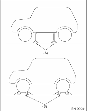
(A) | Rigid rack |
(B) | Free roller |
2. SUBARU SELECT MONITOR
1. Check that no DTC remains after clearing memory. Clear Memory Mode">
2. Warm up the engine.
3. Prepare the Subaru Select Monitor kit. General Description > PREPARATION TOOL">
4. Prepare PC with Subaru Select Monitor installed.
5. Connect the USB cable to the DST-i and the USB port on the personal computer (dedicated port for the Subaru Select Monitor).
NOTE:
The dedicated port for the Subaru Select Monitor means the USB port which was used to install the Subaru Select Monitor.
6. Connect the diagnosis cable to DST-i.
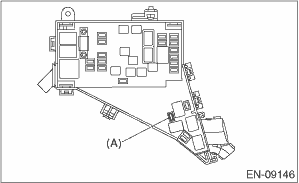
7. Install the delivery (test) mode fuse (A).
CAUTION:
Do not use any fuses that are installed on the vehicle.
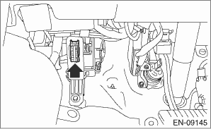
8. Connect the DST-i to the data link connector located in the lower portion of the instrument panel (on the driver’s side).
CAUTION:
Do not connect the scan tools except for Subaru Select Monitor and general scan tool.
9. Start the PC.
10. Turn the ignition switch to ON (engine OFF) and run the “PC application for Subaru Select Monitor”.
11. On «Start» display, select «Diagnosis».
12. On «Vehicle selection» display, input the vehicle information and select «Confirmed».
13. On «Main Menu» display, select «Each System».
14. On «Select System» display, select «Engine Control System» and then select «Enter».
15. On «Select Function» display, select «Dealer Check Mode Procedure» and then select «Enter».
16. When «Perform Inspection (Dealer Check) Mode ?» is shown on the screen, click the «Next» button.
17. Perform subsequent procedures as instructed on the display screen.
• If trouble still remains in the memory, the corresponding DTC appears on the display screen.
NOTE:
• For detailed operation procedures, refer to “Application help”.
• For details concerning DTC, refer to “List of Diagnostic Trouble Code (DTC)”.
List of Diagnostic Trouble Code (DTC)">
• Release the parking brake.
• The rotating speed difference between front and rear wheels may illuminate the warning light, but this does not indicate a malfunction. When engine control system diagnosis is finished, perform the VDC memory clearance procedure of self-diagnosis function. Clear Memory Mode">
3. GENERAL SCAN TOOL
1. Check that no DTC remains after clearing memory. Clear Memory Mode">
2. Warm up the engine.
3. Install the delivery (test) mode fuse (A).
CAUTION:
Do not use any fuses that are installed on the vehicle.
4. Connect the general scan tool to data link connector located in the lower portion of the instrument panel (on the driver’s side).
CAUTION:
Do not connect the scan tools except for Subaru Select Monitor and general scan tool.
5. Start the engine.
NOTE:
• Ensure the selector lever is placed in the “P” range before starting. (CVT model)
• Depress the clutch pedal when starting engine. (MT model)
6. Turn the neutral position switch to ON using select lever or gear shift lever.
7. Depress the brake pedal to turn the brake switch ON. (CVT model)
8. Keep the engine speed in 2,500 — 3,000 rpm range for 40 seconds.
9. Place the select lever or gear shift lever in “D” position (CVT model) or “1st gear” (MT model) and drive the vehicle at 5 to 10 km/h (3 to 6 MPH).
NOTE:
• For AWD model, release the parking brake.
• The rotating speed difference between front and rear wheels may illuminate the ABS warning light, but this does not indicate a malfunction. When engine control system diagnosis is finished, perform the VDC memory clearance procedure of self-diagnosis function. Clear Memory Mode">
10. Using the general scan tool, check for DTC and record the result(s).
NOTE:
• For detailed operation procedures, refer to “Application help”.
• For details concerning DTC, refer to “List of Diagnostic Trouble Code (DTC)”.
List of Diagnostic Trouble Code (DTC)">
 General scan tool Operation
ENGINE (DIAGNOSTICS)(H4DO) > General Scan ToolOPERATION1. HOW TO USE GENERAL SCAN TOOL1. Prepare a scan tool (general scan tool) required by SAE J1978.2. Connect the general scan tool to data link ...
 List of diagnostic trouble code (dtc) List
ENGINE (DIAGNOSTICS)(H4DO) > List of Diagnostic Trouble Code (DTC)LISTDTCItemNoteB1570ANTENNA Diagnostic Procedure with Diagnostic Trouble Code (DTC) > DTC B1570 ANTENNA">B1571REFERENCE ...
Other materials:
Removal
EXTERIOR/INTERIOR TRIM > Roof RailREMOVAL1. Remove the trim panel - roof. Roof Trim > REMOVAL">2. Remove the curtain airbag module. Curtain Airbag Module > REMOVAL">CAUTION:• Before handling the airbag system components, refer to “CAUTION” of “Gener ...
Checking the coolant level
WARNING
Never attempt to remove the radiator
cap until the engine has been
shut off and has cooled down
completely. Since the coolant is
under pressure, you may suffer
serious burns from a spray of boiling
hot coolant when the cap is
removed.
"FULL" level mark
"LOW" level mark
C ...
Removal
EXTERIOR/INTERIOR TRIM > Cowl PanelREMOVAL1. Open the front hood.2. Remove the arm assembly - windshield wiper. Front Wiper Arm > REMOVAL">3. Remove the cowl panel - side.(1) Remove the clips.(2) Release the claws, and then remove the cowl panel - side.CAUTION:Pulling with excessive f ...
