Subaru Crosstrek Service Manual: Electrical specification
TIRE PRESSURE MONITORING SYSTEM (DIAGNOSTICS) > Control Module I/O Signal
ELECTRICAL SPECIFICATION
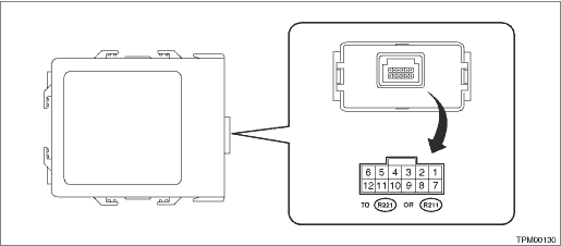
Terminal No. | Content | Measured value and measuring conditions | Remarks |
1 | — | — | — |
2 | — | — | — |
3 | — | — | — |
4 | Ignition power supply | 10 — 13 V (when the ignition switch is ON) | — |
5 | GND | 0 V (always) | — |
6 | Battery power supply | 10 — 13 V (always) | — |
7 | — | — | — |
8 | — | — | — |
9 | — | — | — |
10 | — | — | — |
11 | Body integrated unit | — | — |
12 | — | — | — |

 Wiring diagram
TIRE PRESSURE MONITORING SYSTEM (DIAGNOSTICS) > Control Module I/O SignalWIRING DIAGRAMRefer to “Tire Pressure Monitoring System” in the wiring diagram. Tire Pressure Monitoring System ...
Other materials:
Dtc u1651 lost communication with meter (uart)
INSTRUMENTATION/DRIVER INFO (DIAGNOSTICS) > Diagnostic Procedure with Diagnostic Trouble Code (DTC)DTC U1651 LOST COMMUNICATION WITH METER (UART)DTC detecting condition:UART data from combination meter is not received.Trouble symptom:LCD is not displayed.Wiring diagram:Multi-function display (MFD ...
Dtc c0074 master cylinder pressure sensor output
VEHICLE DYNAMICS CONTROL (VDC) (DIAGNOSTICS) > Diagnostic Procedure with Diagnostic Trouble Code (DTC)DTC C0074 MASTER CYLINDER PRESSURE SENSOR OUTPUTDTC detecting condition:Defective pressure sensorTrouble symptom:• ABS does not operate.• VDC does not operate.• EyeSight does no ...
Removal
SECURITY AND LOCKS > Immobilizer AntennaREMOVAL1. MODEL WITHOUT KEYLESS ACCESS WITH PUSH BUTTON START1. Disconnect the ground cable from battery. NOTE">2. Remove the cover assembly - column.(1) Remove the screws by turning the steering wheel to right and left.(2) Release the claw, and re ...
