Subaru Crosstrek Service Manual: Removal
SECURITY AND LOCKS > Immobilizer Antenna
REMOVAL
1. MODEL WITHOUT KEYLESS ACCESS WITH PUSH BUTTON START
1. Disconnect the ground cable from battery. NOTE">
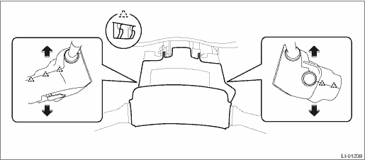
2. Remove the cover assembly - column.
(1) Remove the screws by turning the steering wheel to right and left.
(2) Release the claw, and remove the cover assembly - column UPR and the cover assembly - column LWR.
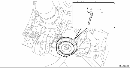
3. Remove the immobilizer antenna assembly.
(1) Disconnect the connector.
(2) Release two claws using a flat tip screwdriver or similar tool wrapped with a protection tape, and remove the immobilizer antenna assembly.
CAUTION:
Do not apply excessive force to disengage the lock of immobilizer antenna assembly. Otherwise they may be broken because those parts are the products made of a plastic.
2. MODEL WITH KEYLESS ACCESS WITH PUSH BUTTON START
NOTE:
Immobilizer antenna is integrated with the push button ignition switch.
1. Remove the cover assembly - instrument panel LWR driver. Instrument Panel Lower Cover > REMOVAL">
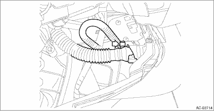
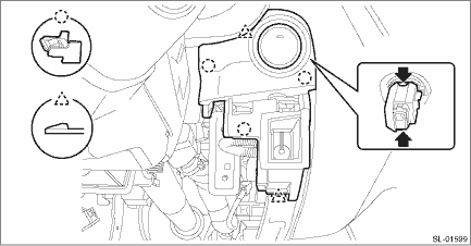
2. Remove the push button ignition switch.
(1) Disconnect the connector, and remove the aspirator hose.
(2) Release the claws, and then remove the panel - switch.
(3) Release the claws, and then remove the push button ignition switch from the panel - switch.
 Installation
SECURITY AND LOCKS > Immobilizer AntennaINSTALLATIONInstall each part in the reverse order of removal. ...
 Impact sensor
...
Other materials:
Preparation tool
WHEEL AND TIRE SYSTEM > General DescriptionPREPARATION TOOL1. GENERAL TOOLTOOL NAMEREMARKSAir pressure gaugeUsed for measuring tire air pressure.Dial gaugeUsed for measuring wheel runout.Wheel balancerUsed for adjusting wheel balance.Circuit testerUsed for measuring resistance, voltage and curren ...
Dtc p0966 pressure control solenoid "b" control circuit low
CONTINUOUSLY VARIABLE TRANSMISSION (DIAGNOSTICS) > Diagnostic Procedure with Diagnostic Trouble Code (DTC)DTC P0966 PRESSURE CONTROL SOLENOID "B" CONTROL CIRCUIT LOWDTC detecting condition:Immediately at fault recognitionTrouble symptom:Excessive shift shockCAUTION:Use the check board w ...
Choosing a child restraint system
When selecting a child restraint system for the Subaru Ascent, it is essential
to choose a model that matches the child’s age, weight, and height to ensure maximum
safety and proper protection during every trip. The correct child restraint system
plays a critical role in reducing injury ...
