
Subaru Crosstrek Service Manual: Electrical specification
OCCUPANT DETECTION SYSTEM (DIAGNOSTICS) > Control Module I/O Signal
ELECTRICAL SPECIFICATION
CAUTION:
Never remove the occupant detection control module, occupant detection sensor or seat frame because they are integrated into one unit.
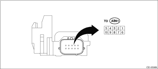
Terminal No. | Terminal name | Input/Output value | Note |
1 | Airbag CM communication (FSR+) | — | Communication line |
2 | Not used | — | — |
3 | Not used | — | — |
4 | Buckle switch − (BER−) | 0 V | Switch ground |
5 | Not used | — | — |
6 | IG power supply (IG) | 8 — 16 V | When ignition SW is ON |
7 | Not used | — | — |
8 | Buckle switch+ | 0 — IG voltage | Ignition voltage when the switch is ON |
9 | Airbag CM communication (FSR−) | 0 V | GND |
10 | Not used | — | — |

 Wiring diagram
OCCUPANT DETECTION SYSTEM (DIAGNOSTICS) > Control Module I/O SignalWIRING DIAGRAMRefer to “Occupant Detection System” in the wiring diagram. Occupant Detection System > WIRING DIAGR ...
Other materials:
Location
ENTERTAINMENT > Relay and FuseLOCATIONRelay & fuse boxFuse 20 A (rear accessory power supply socket)(A)Fuse 10 A (front accessory power supply socket)(B)Fuse 10 A (audio, navigation unit, AUX input terminal, data communication module*1)(C)Fuse 15 A (data communication module*1)(D)*1: Model wi ...
Dtc u1433 invalid data received from eyesight
CONTINUOUSLY VARIABLE TRANSMISSION (DIAGNOSTICS) > Diagnostic Procedure with Diagnostic Trouble Code (DTC)DTC U1433 INVALID DATA RECEIVED FROM EyeSightNOTE:Refer to “LAN SYSTEM (DIAGNOSTICS)” for diagnostic procedure. Basic Diagnostic Procedure">1. OUTLINE OF DIAGNOSIS• ...
Preparation tool
SECURITY AND LOCKS > General DescriptionPREPARATION TOOL1. SPECIAL TOOLILLUSTRATIONTOOL NUMBERDESCRIPTIONREMARKS — SUBARU SELECT MONITOR 4Used for setting of each function and troubleshooting for electrical system.NOTE:For detailed operation procedures of Subaru Select Monitor 4, refer to &ldqu ...
