Subaru Crosstrek Service Manual: Electrical specification
CONTROL SYSTEMS > AT Shift Lock Control System
ELECTRICAL SPECIFICATION
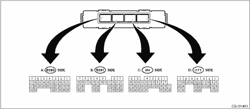
• Model without push button ignition switch
Item | Connector No. | Terminal No. | Input/Output signal |
Measured value and measuring conditions | |||
Battery power supply | B281 | 6 | 9 — 16 V |
7 | |||
i84 | 6 | ||
Ignition power supply | B280 | 32 | 10 — 15 V when ignition switch is at ACC. |
B281 | 3 | 10 — 15 V when ignition switch is at ON or START. | |
TCM (“P” range) | B281 | 20 | Can not be measured because of digital communication |
28 | |||
Stop light and brake switch | B280 | 10 | 9 — 16 V when the stop light & brake switch is ON. 0 V when the stop light & brake switch is OFF. |
“P” range switch | B281 | 18 | Less than 1.5 V when select lever is in “P” range 8 V or more when select lever is in positions other than “P” range. |
Solenoid unit signal | B281 | 5 | 8.5 — 16 V when shift lock is released. 0 V when shift lock is operating. |
Key warning switch signal | B280 | 4 | 9 — 16 V when key is inserted. 0 V when key is removed. |
Key lock solenoid signal | B281 | 4 | 7.5 — 16 V when the key is inserted with the select lever shifted in positions other than “P” range. 0 V at other conditions than above. |
Ground | B280 | 1 | — |
i84 | 1 | ||
Delivery (test) mode signal | i84 | 27 | Can not be measured because of digital communication |
35 |
• Model with push button ignition switch
Item | Connector No. | Terminal No. | Input/Output signal |
Measured value and measuring conditions | |||
Battery power supply | B281 | 6 | 9 — 16 V |
7 | |||
i84 | 6 | ||
Ignition power supply | B280 | 32 | 10 — 15 V when ignition switch is at ACC. |
B281 | 3 | 10 — 15 V when ignition switch is at ON or START. | |
TCM (“P” range) | B281 | 20 | Can not be measured because of digital communication |
28 | |||
Stop light and brake switch | B280 | 10 | 9 — 16 V when the stop light & brake switch is ON. 0 V when the stop light & brake switch is OFF. |
“P” range switch | B281 | 18 | Less than 1.5 V when select lever is in “P” range 8 V or more when select lever is in positions other than “P” range. |
Solenoid unit signal | B281 | 5 | 8.5 — 16 V when shift lock is released. 0 V when shift lock is operating. |
Ground | B280 | 1 | — |
i84 | 1 | ||
Delivery (test) mode signal | i84 | 27 | Can not be measured because of digital communication |
35 |

 Inspection
CONTROL SYSTEMS > AT Shift Lock Control SystemINSPECTION1. SHIFT LOCK OPERATION• Model without push button ignition switchSTEPCHECKYESNO1.CHECK COMMUNICATION OF SUBARU SELECT MONITOR.1) Turn ...
Other materials:
Cooling fan, hose and connections
Your vehicle employs an electric cooling
fan which is thermostatically controlled to
operate when the engine coolant reaches
a specific temperature.
If the radiator cooling fan does not operate
even when the coolant temperature high
warning light blinks or illuminates in RED,
the cooling fa ...
Removal
EMISSION CONTROL (AUX. EMISSION CONTROL DEVICES)(H4DO) > PCV ValveREMOVALCAUTION:Do not remove unless the PCV valve is broken.1. Disconnect the PCV hose from the intake manifold and the PCV valve, and then remove the PCV hose.2. Remove the clip (A) holding the air breather hose from the engine ha ...
Removal
INSTRUMENTATION/DRIVER INFO > Combination MeterREMOVAL1. Disconnect the ground cable from battery. NOTE">2. Release the lock, tilt the steering column to the lowest end and fully extend the column by the telescopic system.3. Release the screws, clips and claws, and remove the visor - com ...
