Subaru Crosstrek Service Manual: Electrical component location Location
CONTINUOUSLY VARIABLE TRANSMISSION (DIAGNOSTICS) > Electrical Component Location
LOCATION
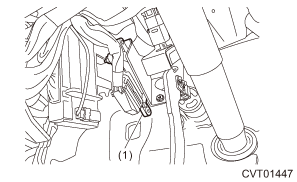
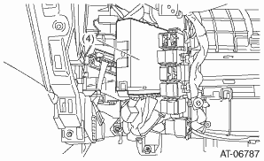
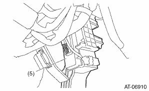
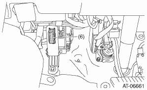
1. CONTROL MODULE

(1) | Transmission control module (TCM) | (3) | AWD light | (5) | Body integrated unit |
(2) | AT OIL TEMP light | (4) | Engine control module (ECM) | (6) | Data link connector |


2. SENSOR
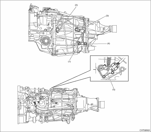
(1) | Secondary speed sensor | (3) | Primary speed sensor | (5) | Inhibitor switch |
(2) | Turbine speed sensor | (4) | Secondary pressure sensor |
3. SOLENOID
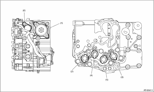
(1) | Secondary solenoid | (3) | Lock-up duty solenoid | (5) | Primary UP solenoid |
(2) | AWD solenoid | (4) | Primary DOWN solenoid | (6) | F&R solenoid |
 Drive cycle Procedure
CONTINUOUSLY VARIABLE TRANSMISSION (DIAGNOSTICS) > Drive CyclePROCEDUREIt is possible to complete diagnosis of the DTC by performing the indicated drive cycle. After the repair for the DTC, perform ...
 Inspection mode Procedure
CONTINUOUSLY VARIABLE TRANSMISSION (DIAGNOSTICS) > Inspection ModePROCEDURE Road Test"> ...
Other materials:
Dtc b2301 rear radar circuit high
Blind Spot Detection/Rear Cross Traffic Alert (DIAGNOSTICS) > Diagnostic Procedure with Diagnostic Trouble Code (DTC)DTC B2301 REAR RADAR CIRCUIT HIGHDTC detecting condition:• Open circuit or short circuit to power supply in harness between radar sensor and outer mirror assembly.• Ope ...
Inspection
COMMUNICATION SYSTEM > Relay and FuseINSPECTION1. CHECK FUSE1. Remove the fuse and check visually.2. If the fuse is blown out, replace the fuse.2. CHECK RELAY1. Check the resistance between relay terminals.Terminal No.Inspection conditionsSpecificationCircuit1 — 2Always1 M? or more1 — 2Apply ...
Dtc c1731 g sensor abnormal
VEHICLE DYNAMICS CONTROL (VDC) (DIAGNOSTICS) > Diagnostic Procedure with Diagnostic Trouble Code (DTC)DTC C1731 G SENSOR ABNORMALNOTE:For the diagnostic procedure, refer to “DTC C1732 LATERAL G SENSOR”. Diagnostic Procedure with Diagnostic Trouble Code (DTC) > DTC C1732 LATERAL G ...
