Subaru Crosstrek Service Manual: Dtc u1650 invalid data received from meter (uart)
INSTRUMENTATION/DRIVER INFO (DIAGNOSTICS) > Diagnostic Procedure with Diagnostic Trouble Code (DTC)
DTC U1650 INVALID DATA RECEIVED FROM METER (UART)
DTC DETECTING CONDITION:
There is an abnormality in UART data from combination meter.
TROUBLE SYMPTOM:
LCD is not displayed.
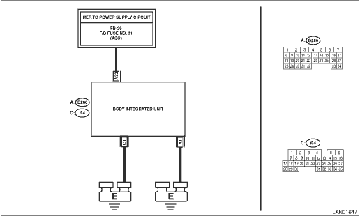
WIRING DIAGRAM:
Clearance Light and Illumination Light System Clearance Light and Illumination Light System">
| STEP | CHECK | YES | NO |
1.CHECK LAN SYSTEM.
Read the DTC of body integrated unit and LAN system using Subaru Select Monitor. Read Diagnostic Trouble Code (DTC)"> Read Diagnostic Trouble Code (DTC)">
Is any DTC other than U1650 displayed?
Perform the diagnosis according to DTC.
Diagnostic Procedure with Diagnostic Trouble Code (DTC) > DTC U1650 INVALID DATA RECEIVED FROM METER (UART)">Go to Step 2.
2.CHECK FUSE.
Check the fuse No. 31 in the fuse & relay box.
Is the fuse OK?
Diagnostic Procedure with Diagnostic Trouble Code (DTC) > DTC U1650 INVALID DATA RECEIVED FROM METER (UART)">Go to Step 3.
Replace the fuse. When the fuse is blown easily, check the wiring.
3.CHECK HARNESS.
1) Disconnect the body integrated unit connector.
2) Turn the ignition switch OFF > ACC.
3) Measure the voltage between body integrated unit connector and chassis ground using tester.
Connector & terminal
(B280) No. 32 (+) — Chassis ground (−):
Is the voltage 10 V or more?
Diagnostic Procedure with Diagnostic Trouble Code (DTC) > DTC U1650 INVALID DATA RECEIVED FROM METER (UART)">Go to Step 4.
Repair the ACC power supply circuit of the body integrated unit.
4.CHECK CURRENT DATA OF INTEGRATED UNIT.
1) Connect the Subaru Select Monitor.
2) Turn the ignition switch to ON.
3) Check the current data «ACC voltage» of the body integrated unit. Read Current Data">
Is the voltage 10 V or more?
Diagnostic Procedure with Diagnostic Trouble Code (DTC) > DTC U1650 INVALID DATA RECEIVED FROM METER (UART)">Go to Step 5.
Inspect and correct the body integrated unit connector. If there is no abnormality, replace the body integrated unit. Body Integrated Unit"> (There may be a poor contact in the body integrated unit connector ((B280) terminal No. 32), or an internal malfunction of the integrated unit.) (If the current data indicates ACC voltage value ≈ Battery voltage, there will be no malfunction up to inside of the integrated unit. If U1650 is still detected in this condition as current malfunction, perform step 5 and subsequent procedures.)
5.CHECK CONNECTOR.
1) Disconnect the MFD connector and the combination meter connector.
2) Connect the disconnected connectors.
3) Read the DTC of the MFD using the Subaru Select Monitor. Read Diagnostic Trouble Code (DTC)">
Is DTC U1650 a current malfunction?
Diagnostic Procedure with Diagnostic Trouble Code (DTC) > DTC U1650 INVALID DATA RECEIVED FROM METER (UART)">Go to Step 6.
There was poor contact of connector. Repair the poor contact of connector. (Poor contact in combination connector (i10) terminal No. 20 or MFD connector (i122) terminal No. 9)
6.CHECK COMBINATION METER.
1) Replace the combination meter. Combination Meter">
2) Read the DTC of the MFD using the Subaru Select Monitor. Read Diagnostic Trouble Code (DTC)">
Is DTC U1650 a current malfunction?
Replace the MFD. Multi-function Display (MFD)">
There was something wrong with the combination meter.
 Dtc u1201 can-hs counter abnormal
INSTRUMENTATION/DRIVER INFO (DIAGNOSTICS) > Diagnostic Procedure with Diagnostic Trouble Code (DTC)DTC U1201 CAN-HS COUNTER ABNORMALDetected when CAN data is abnormal.NOTE:Perform the diagnosis for ...
 Dtc u1651 lost communication with meter (uart)
INSTRUMENTATION/DRIVER INFO (DIAGNOSTICS) > Diagnostic Procedure with Diagnostic Trouble Code (DTC)DTC U1651 LOST COMMUNICATION WITH METER (UART)DTC detecting condition:UART data from combination m ...
Other materials:
Operation
KEYLESS ACCESS WITH PUSH BUTTON START SYSTEM (DIAGNOSTICS) > Read Current DataOPERATION1. On «Start» display, select «Diagnosis».2. On «Vehicle selection» display, input the target vehicle information and select «Confirmed».3. On «Main Menu» display, select «Each System».4. On «Selec ...
Adjustment
CONTINUOUSLY VARIABLE TRANSMISSION(TR580) > Inhibitor SwitchADJUSTMENT1. Shift the select lever to “N” range.2. Loosen the two bolts holding the inhibitor switch.3. Insert the ST vertically into the holes of the shifter arm and switch body.ST 499267300STOPPER PIN4. Tighten the two ...
Electrical component location Location
HVAC SYSTEM (AUTO A/C) (DIAGNOSTICS) > Electrical Component LocationLOCATION1. OUTSIDE VEHICLE(1)A/C compressor(3)Pressure switch(4)Ambient sensor(2)A/C relay 2. COMPARTMENT(1)Air mix door actuator LH*2(5)Intake door actuator(9)A/C control panel(2)In-vehicle sensor(6)Mode door actuator(10)Blow ...
