Subaru Crosstrek Service Manual: Dtc p2097 post catalyst fuel trim system too rich bank 1
ENGINE (DIAGNOSTICS)(H4DO) > Diagnostic Procedure with Diagnostic Trouble Code (DTC)
DTC P2097 POST CATALYST FUEL TRIM SYSTEM TOO RICH BANK 1
DTC detecting condition:
Detected when two consecutive driving cycles with fault occur.
CAUTION:
After servicing or replacing faulty parts, perform Clear Memory Mode Clear Memory Mode > OPERATION"> , and Inspection Mode Inspection Mode > PROCEDURE">.
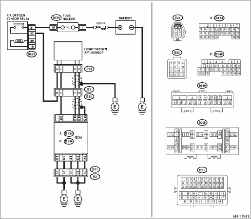
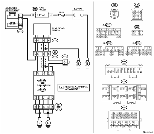
Wiring diagram:
Engine electrical system Engine Electrical System">
| STEP | CHECK | YES | NO |
1.CHECK FOR ANY OTHER DTC ON DISPLAY.
Is any other DTC displayed?
Check DTC using “List of Diagnostic Trouble Code (DTC)”. List of Diagnostic Trouble Code (DTC)">
Diagnostic Procedure with Diagnostic Trouble Code (DTC) > DTC P2097 POST CATALYST FUEL TRIM SYSTEM TOO RICH BANK 1">Go to Step 2.
2.CHECK FRONT OXYGEN (A/F) SENSOR CONNECTOR AND COUPLING CONNECTOR.
Has water entered the connector?
Completely remove any water inside.
Diagnostic Procedure with Diagnostic Trouble Code (DTC) > DTC P2097 POST CATALYST FUEL TRIM SYSTEM TOO RICH BANK 1">Go to Step 3.
3.CHECK HARNESS BETWEEN ECM AND FRONT OXYGEN (A/F) SENSOR CONNECTOR.
1) Turn the ignition switch to OFF.
2) Disconnect the connector from ECM.
3) Disconnect the connectors from front oxygen (A/F) sensor.
4) Measure the resistance of harness between ECM connector and front oxygen (A/F) sensor connector.
Connector & terminal
(B136) No. 19 — (E24) No. 3:
(B136) No. 18 — (E24) No. 4:
Is the resistance less than 1 ??
Diagnostic Procedure with Diagnostic Trouble Code (DTC) > DTC P2097 POST CATALYST FUEL TRIM SYSTEM TOO RICH BANK 1">Go to Step 4.
Repair the harness and connector.
NOTE:
In this case, repair the following item:
• Open circuit in harness between ECM connector and front oxygen (A/F) sensor connector
• Poor contact of coupling connector
4.CHECK HARNESS BETWEEN ECM AND FRONT OXYGEN (A/F) SENSOR CONNECTOR.
Measure the resistance between ECM connector and chassis ground.
Connector & terminal
(B136) No. 19 — Chassis ground:
(B136) No. 18 — Chassis ground:
Is the resistance 1 M? or more?
Diagnostic Procedure with Diagnostic Trouble Code (DTC) > DTC P2097 POST CATALYST FUEL TRIM SYSTEM TOO RICH BANK 1">Go to Step 5.
Repair the short circuit to ground in harness between ECM connector and front oxygen (A/F) sensor connector.
5.CHECK OUTPUT SIGNAL FOR ECM.
1) Connect the connector to ECM.
2) Turn the ignition switch to ON.
3) Measure the voltage between front oxygen (A/F) sensor connector and chassis ground.
Connector & terminal
(E24) No. 3 (+) — Chassis ground (−):
Is the voltage 4.5 V or more?
Diagnostic Procedure with Diagnostic Trouble Code (DTC) > DTC P2097 POST CATALYST FUEL TRIM SYSTEM TOO RICH BANK 1">Go to Step 7.
Diagnostic Procedure with Diagnostic Trouble Code (DTC) > DTC P2097 POST CATALYST FUEL TRIM SYSTEM TOO RICH BANK 1">Go to Step 6.
6.CHECK OUTPUT SIGNAL FOR ECM.
Measure the voltage between front oxygen (A/F) sensor connector and chassis ground.
Connector & terminal
(E24) No. 4 (+) — Chassis ground (−):
Is the voltage 4.95 V or more?
Diagnostic Procedure with Diagnostic Trouble Code (DTC) > DTC P2097 POST CATALYST FUEL TRIM SYSTEM TOO RICH BANK 1">Go to Step 7.
Diagnostic Procedure with Diagnostic Trouble Code (DTC) > DTC P2097 POST CATALYST FUEL TRIM SYSTEM TOO RICH BANK 1">Go to Step 8.
7.CHECK OUTPUT SIGNAL FOR ECM.
Measure the voltage between front oxygen (A/F) sensor connector and chassis ground.
Connector & terminal
(E24) No. 3 (+) — Chassis ground (−):
(E24) No. 4 (+) — Chassis ground (−):
Is the voltage 8 V or more?
Repair the short circuit to power in the harness between ECM connector and front oxygen (A/F) sensor connector. After repair, replace the ECM. Engine Control Module (ECM)">
Repair the poor contact of ECM connector.
8.CHECK EXHAUST SYSTEM.
Are there holes or loose bolts on exhaust system?
Repair the exhaust system.
Diagnostic Procedure with Diagnostic Trouble Code (DTC) > DTC P2097 POST CATALYST FUEL TRIM SYSTEM TOO RICH BANK 1">Go to Step 9.
9.CHECK AIR INTAKE SYSTEM.
Are there holes, loose bolts or disconnection of hose on air intake system?
Repair the air intake system.
Diagnostic Procedure with Diagnostic Trouble Code (DTC) > DTC P2097 POST CATALYST FUEL TRIM SYSTEM TOO RICH BANK 1">Go to Step 10.
10.CHECK FUEL PRESSURE.
WARNING:
Place “NO OPEN FLAMES” signs near the working area.
CAUTION:
Be careful not to spill fuel.
1) Connect the front oxygen (A/F) sensor connector.
2) Measure the fuel pressure. Fuel Pressure > INSPECTION">
CAUTION:
Release fuel pressure before removing the fuel pressure gauge.
Is the measured value 340 — 400 kPa (3.5 — 4.1 kg/cm2, 49 — 58 psi)?
Diagnostic Procedure with Diagnostic Trouble Code (DTC) > DTC P2097 POST CATALYST FUEL TRIM SYSTEM TOO RICH BANK 1">Go to Step 11.
Check the fuel pump and fuel delivery line. Fuel Pump > INSPECTION"> Fuel Delivery and Evaporation Lines > INSPECTION">
11.CHECK ENGINE COOLANT TEMPERATURE SENSOR.
1) Start the engine and warm up completely.
2) Read the value of «Coolant Temp.» using the Subaru Select Monitor or a general scan tool.
NOTE:
• Subaru Select Monitor
For detailed operation procedures, refer to “Current Data Display For Engine”. Subaru Select Monitor">
• General scan tool
For detailed operation procedures, refer to the general scan tool operation manual.
Is the value of «Coolant Temp.» 75°C (167°F) or more?
Diagnostic Procedure with Diagnostic Trouble Code (DTC) > DTC P2097 POST CATALYST FUEL TRIM SYSTEM TOO RICH BANK 1">Go to Step 12.
Replace the engine coolant temperature sensor. Engine Coolant Temperature Sensor">
12.CHECK MASS AIR FLOW AND INTAKE AIR TEMPERATURE SENSOR.
1) Start the engine and warm up engine until coolant temperature is higher than 75°C (167°F).
2) For CVT models, set the select lever to “P” range or “N” range, and for MT models, place the gear shift lever in the neutral position.
3) Turn the A/C switch to OFF.
4) Turn all the accessory switches to OFF.
5) Read the value of «Mass Air Flow» using the Subaru Select Monitor or a general scan tool.
NOTE:
• Subaru Select Monitor
For detailed operation procedures, refer to “Current Data Display For Engine”. Subaru Select Monitor">
• General scan tool
For detailed operation procedures, refer to the general scan tool operation manual.
Is the value of «Mass Air Flow» 2.0 — 5.0 g/s (0.26 — 0.66 lb/m)?
Diagnostic Procedure with Diagnostic Trouble Code (DTC) > DTC P2097 POST CATALYST FUEL TRIM SYSTEM TOO RICH BANK 1">Go to Step 13.
Replace the mass air flow and intake air temperature sensor. Mass Air Flow and Intake Air Temperature Sensor">
13.CHECK MASS AIR FLOW AND INTAKE AIR TEMPERATURE SENSOR.
1) Start the engine and warm up engine until coolant temperature is higher than 75°C (167°F).
2) For CVT models, set the select lever to “P” range or “N” range, and for MT models, place the gear shift lever in the neutral position.
3) Turn the A/C switch to OFF.
4) Turn all the accessory switches to OFF.
5) Open the front hood.
6) Measure the ambient temperature.
7) Read the value of «Intake Air Temp.» using the Subaru Select Monitor or a general scan tool.
NOTE:
• Subaru Select Monitor
For detailed operation procedures, refer to “Current Data Display For Engine”. Subaru Select Monitor">
• General scan tool
For detailed operation procedures, refer to the general scan tool operation manual.
Subtract ambient temperature from «Intake Air Temp.». Is the obtained value −10 — 50°C (−18 — 90°F)?
Diagnostic Procedure with Diagnostic Trouble Code (DTC) > DTC P2097 POST CATALYST FUEL TRIM SYSTEM TOO RICH BANK 1">Go to Step 14.
Check the mass air flow and intake air temperature sensor. Mass Air Flow and Intake Air Temperature Sensor">
14.CHECK REAR OXYGEN SENSOR DATA.
1) Warm up the engine until engine coolant temperature is higher than 75°C (167°F), and keep the engine speed at 3,000 rpm. (2 minutes maximum)
2) Read the value of «Rear O2 Sensor Voltage» using the Subaru Select Monitor or a general scan tool.
NOTE:
• Depress the clutch pedal. (MT model)
• Subaru Select Monitor
For detailed operation procedures, refer to “Current Data Display For Engine”. Subaru Select Monitor">
• General scan tool
For detailed operation procedures, refer to the general scan tool operation manual.
Is the value of «Rear O2 Sensor Voltage» 0.490 V or more?
Diagnostic Procedure with Diagnostic Trouble Code (DTC) > DTC P2097 POST CATALYST FUEL TRIM SYSTEM TOO RICH BANK 1">Go to Step 15.
Diagnostic Procedure with Diagnostic Trouble Code (DTC) > DTC P2097 POST CATALYST FUEL TRIM SYSTEM TOO RICH BANK 1">Go to Step 16.
15.CHECK REAR OXYGEN SENSOR DATA.
1) Warm up the engine until engine coolant temperature is higher than 75°C (167°F), and rapidly reduce the engine speed from 3,000 rpm.
2) Read the value of «Rear O2 Sensor Voltage» using the Subaru Select Monitor or a general scan tool.
NOTE:
• Depress the clutch pedal. (MT model)
• Subaru Select Monitor
For detailed operation procedures, refer to “Current Data Display For Engine”. Subaru Select Monitor">
• General scan tool
For detailed operation procedures, refer to the general scan tool operation manual.
Is the value of «Rear O2 Sensor Voltage» 0.250 V or less?
Diagnostic Procedure with Diagnostic Trouble Code (DTC) > DTC P2097 POST CATALYST FUEL TRIM SYSTEM TOO RICH BANK 1">Go to Step 17.
Diagnostic Procedure with Diagnostic Trouble Code (DTC) > DTC P2097 POST CATALYST FUEL TRIM SYSTEM TOO RICH BANK 1">Go to Step 16.
16.CHECK REAR OXYGEN SENSOR CONNECTOR AND COUPLING CONNECTOR.
Has water entered the connector?
Completely remove any water inside.
Diagnostic Procedure with Diagnostic Trouble Code (DTC) > DTC P2097 POST CATALYST FUEL TRIM SYSTEM TOO RICH BANK 1">Go to Step 18.
17.CHECK FRONT OXYGEN (A/F) SENSOR USING REAR OXYGEN SENSOR SIGNAL.
1) Warm up the engine until engine coolant temperature is higher than 75°C (167°F), then keep the engine idling for 5 minutes or more.
2) Read the value of «Rear O2 Sensor Voltage» using the Subaru Select Monitor or a general scan tool.
NOTE:
• Subaru Select Monitor
For detailed operation procedures, refer to “Current Data Display For Engine”. Subaru Select Monitor">
• General scan tool
For detailed operation procedures, refer to the general scan tool operation manual.
Is the value in «Rear O2 Sensor Voltage» kept at 0.8 V or more for 5 minutes or more?
Replace the front oxygen (A/F) sensor. Front Oxygen (A/F) Sensor">
Diagnostic Procedure with Diagnostic Trouble Code (DTC) > DTC P2097 POST CATALYST FUEL TRIM SYSTEM TOO RICH BANK 1">Go to Step 18.
18.CHECK HARNESS BETWEEN ECM AND REAR OXYGEN SENSOR CONNECTOR.
1) Turn the ignition switch to OFF.
2) Disconnect the connector from ECM.
3) Disconnect the connector from rear oxygen sensor.
4) Measure the resistance of harness between ECM connector and rear oxygen sensor connector.
Connector & terminal
(B136) No. 21 — (E25) No. 3:
(B135) No. 30 — (E25) No. 4:
Is the resistance less than 1 ??
Diagnostic Procedure with Diagnostic Trouble Code (DTC) > DTC P2097 POST CATALYST FUEL TRIM SYSTEM TOO RICH BANK 1">Go to Step 19.
Repair the harness and connector.
NOTE:
In this case, repair the following item:
• Open circuit in harness between ECM connector and rear oxygen sensor connector
• Poor contact of coupling connector
19.CHECK HARNESS BETWEEN ECM AND REAR OXYGEN SENSOR CONNECTOR.
1) Connect the connector to ECM.
2) Turn the ignition switch to ON.
3) Measure the voltage between rear oxygen sensor connector and chassis ground.
Connector & terminal
(E25) No. 3 (+) — Chassis ground (−):
Is the voltage 0.2 — 0.5 V?
Replace the rear oxygen sensor. Rear Oxygen Sensor">
Repair the harness and connector.
NOTE:
In this case, repair the following item:
• Open circuit in harness between ECM connector and rear oxygen sensor connector
• Poor contact of ECM connector
• Poor contact of coupling connector
1. OUTLINE OF DIAGNOSIS
Detect the malfunction of fuel system from the size of the sub feedback learning value.
Sub feedback learning is being performed. When the learning value goes to the rich side, judge as NG.
2. COMPONENT DESCRIPTION
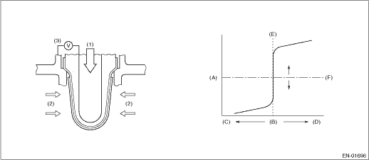
(A) | Electromotive force | (B) | Air fuel ratio | (C) | Lean |
(D) | Rich | (E) | Theoretical air fuel ratio | (F) | Comparative voltage |
(1) | Atmosphere | (2) | Exhaust gas | (3) | Electromotive force |
3. EXECUTION CONDITION
Secondary parameters | Execution condition |
Sub feedback | In operation |
Amount of intake air | ≥ 10 g/s (0.35 oz/s) |
Engine load change every 0.5 engine revs. | < 0.02 g/rev (0 oz/rev) |
4. GENERAL DRIVING CYCLE
Perform the diagnosis continuously when the vehicle is idling or running at a constant speed of 80 km/h (50 MPH) or more.
5. DIAGNOSTIC METHOD
If the duration of time while the following conditions are met is longer than the time indicated, judge as NG.
Malfunction Criteria | Threshold Value |
Sub feedback learning value | ≥ 0.033 (CVT model) ≥ 0.032 (MT model) |
Time needed for diagnosis: 1 s
Malfunction indicator light illumination: Illuminates when malfunction occurs in 2 continuous driving cycles.
 Dtc p2096 post catalyst fuel trim system too lean bank 1
ENGINE (DIAGNOSTICS)(H4DO) > Diagnostic Procedure with Diagnostic Trouble Code (DTC)DTC P2096 POST CATALYST FUEL TRIM SYSTEM TOO LEAN BANK 1DTC detecting condition:Detected when two consecutive dri ...
 Dtc p2101 throttle actuator "a" control motor circuit range/performance
ENGINE (DIAGNOSTICS)(H4DO) > Diagnostic Procedure with Diagnostic Trouble Code (DTC)DTC P2101 THROTTLE ACTUATOR "A" CONTROL MOTOR CIRCUIT RANGE/PERFORMANCEDTC detecting condition:Immediat ...
Other materials:
Preparation tool
COOLING(H4DO) > General DescriptionPREPARATION TOOL1. SPECIAL TOOLILLUSTRATIONTOOL NUMBERDESCRIPTIONREMARKS18355AA000PULLEY WRENCH• Used for removing and installing water pump pulley.• Used with PULLEY WRENCH PIN SET (18334AA030).18334AA030PULLEY WRENCH PIN SET• Used for removin ...
Dtc p0716 input/turbine shaft speed sensor "a" circuit range/performance
CONTINUOUSLY VARIABLE TRANSMISSION (DIAGNOSTICS) > Diagnostic Procedure with Diagnostic Trouble Code (DTC)DTC P0716 INPUT/TURBINE SHAFT SPEED SENSOR "A" CIRCUIT RANGE/PERFORMANCEDTC detecting condition:Immediately at fault recognitionTrouble symptom:• No lock-up occurs.• Sho ...
Other markings
The following makings are also
placed on the sidewall.
Maximum permissible inflation
pressure
The maximum cold inflation pressure
to which this tire may be
inflated. For example, "300 kPa
(44 PSI) MAX. PRESS"
Maximum load rating
The load rating at the maximum
permissible weight load for th ...
