Subaru Crosstrek Service Manual: Dtc p2012 tgv control circuit low bank 2
ENGINE (DIAGNOSTICS)(H4DO) > Diagnostic Procedure with Diagnostic Trouble Code (DTC)
DTC P2012 TGV CONTROL CIRCUIT LOW BANK 2
DTC DETECTING CONDITION:
Immediately at fault recognition
CAUTION:
After servicing or replacing faulty parts, perform Clear Memory Mode Clear Memory Mode > OPERATION"> , and Inspection Mode Inspection Mode > PROCEDURE">.
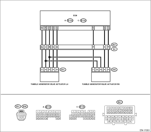
WIRING DIAGRAM:
Engine electrical system Engine Electrical System">
| STEP | CHECK | YES | NO |
1.CHECK HARNESS BETWEEN ECM AND TUMBLE GENERATOR VALVE ACTUATOR LH CONNECTOR.
1) Turn the ignition switch to OFF.
2) Disconnect the connector from ECM.
3) Measure the voltage between ECM connector and chassis ground.
Connector & terminal
(B134) No. 23 (+) — Chassis ground (−):
(B134) No. 24 (+) — Chassis ground (−):
Is the voltage 5 V or more?
Repair the short circuit to power in harness between ECM connector and tumble generator valve actuator LH connector.
Replace the tumble generator valve actuator LH. Tumble Generator Valve Actuator">
1. OUTLINE OF DIAGNOSIS
Detect the open or short circuit of tumble generator valve motor.
Judge as NG when the overcurrent signal is sent from IC after tumble generator valve driving IC diagnosis.
2. COMPONENT DESCRIPTION
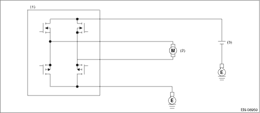
(1) | Engine control module (ECM) | (2) | Tumble generator valve | (3) | Battery |
3. EXECUTION CONDITION
Secondary Parameters | Execution condition |
Battery voltage | ≥ 10.9 V |
TGV command | = Open or = closed |
4. GENERAL DRIVING CYCLE
Always perform the diagnosis continuously.
5. DIAGNOSTIC METHOD
If the duration of time while the following conditions are met is longer than the time indicated, judge as NG.
Malfunction Criteria | Threshold Value |
Overcurrent signal from driver IC Short circuit to GND is detected when IC current > 16 A or Short circuit to B+ is detected when IC current > 14 A | = ON |
Time Needed for Diagnosis: 1 second
Malfunction Indicator Light Illumination: Illuminates as soon as a malfunction occurs.
 Dtc p2009 tgv control circuit low bank 1
ENGINE (DIAGNOSTICS)(H4DO) > Diagnostic Procedure with Diagnostic Trouble Code (DTC)DTC P2009 TGV CONTROL CIRCUIT LOW BANK 1DTC DETECTING CONDITION:Immediately at fault recognitionCAUTION:After ser ...
 Dtc p2096 post catalyst fuel trim system too lean bank 1
ENGINE (DIAGNOSTICS)(H4DO) > Diagnostic Procedure with Diagnostic Trouble Code (DTC)DTC P2096 POST CATALYST FUEL TRIM SYSTEM TOO LEAN BANK 1DTC detecting condition:Detected when two consecutive dri ...
Other materials:
Airbag connector Procedure
AIRBAG SYSTEM > Airbag ConnectorPROCEDURE1. POWER SUPPLY1. How to disconnect:CAUTION:When pulling the slide lock or disconnecting connector, be sure to hold the connector, not the harness.(1) Push the lock (a).(2) While holding down the lock (a), disconnect the connector.2. How to connect:CAUTION ...
Caution
POWER ASSISTED SYSTEM (POWER STEERING) > General DescriptionCAUTION• Wear appropriate work clothing, including a helmet, protective goggles and protective shoes when performing any work.• Before removal, installation or disassembly, be sure to clarify the failure. Avoid unnecessary re ...
Dtc b1817 short in passenger s airbag dual stage - 2nd step (to ground)
AIRBAG SYSTEM (DIAGNOSTICS) > Diagnostic Chart with Trouble CodeDTC B1817 SHORT IN PASSENGER’S AIRBAG DUAL STAGE - 2ND STEP (TO GROUND)Diagnosis start condition:Ignition voltage is 10 V to 16 V.DTC detecting condition:• Airbag main harness circuit is shorted to ground.• Airbag m ...
