Subaru Crosstrek Service Manual: Dtc p2009 tgv control circuit low bank 1
ENGINE (DIAGNOSTICS)(H4DO) > Diagnostic Procedure with Diagnostic Trouble Code (DTC)
DTC P2009 TGV CONTROL CIRCUIT LOW BANK 1
DTC DETECTING CONDITION:
Immediately at fault recognition
CAUTION:
After servicing or replacing faulty parts, perform Clear Memory Mode Clear Memory Mode > OPERATION"> , and Inspection Mode Inspection Mode > PROCEDURE">.
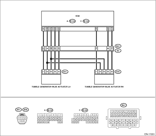
WIRING DIAGRAM:
Engine electrical system Engine Electrical System">
| STEP | CHECK | YES | NO |
1.CHECK HARNESS BETWEEN ECM AND TUMBLE GENERATOR VALVE ACTUATOR RH CONNECTOR.
1) Turn the ignition switch to OFF.
2) Disconnect the connector from ECM.
3) Measure the voltage between ECM connector and chassis ground.
Connector & terminal
(B134) No. 25 (+) — Chassis ground (−):
(B134) No. 14 (+) — Chassis ground (−):
Is the voltage 5 V or more?
Repair the short circuit to power in harness between ECM connector and tumble generator valve actuator RH connector.
Replace the tumble generator valve actuator RH. Tumble Generator Valve Actuator">
1. OUTLINE OF DIAGNOSIS
Detect the open or short circuit of tumble generator valve motor.
Judge as NG when the overcurrent signal is sent from IC after tumble generator valve driving IC diagnosis.
2. COMPONENT DESCRIPTION
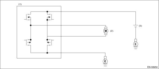
(1) | Engine control module (ECM) | (2) | Tumble generator valve | (3) | Battery |
3. EXECUTION CONDITION
Secondary Parameters | Execution condition |
Battery voltage | ≥ 10.9 V |
TGV command | = Open or = closed |
4. GENERAL DRIVING CYCLE
Always perform the diagnosis continuously.
5. DIAGNOSTIC METHOD
If the duration of time while the following conditions are met is longer than the time indicated, judge as NG.
Malfunction Criteria | Threshold Value |
Overcurrent signal from driver IC Short circuit to GND is detected when IC current > 16 A or Short circuit to B+ is detected when IC current > 14 A | = ON |
Time Needed for Diagnosis: 1 second
Malfunction Indicator Light Illumination: Illuminates as soon as a malfunction occurs.
 Dtc p2007 tgv control stuck closed bank 2
ENGINE (DIAGNOSTICS)(H4DO) > Diagnostic Procedure with Diagnostic Trouble Code (DTC)DTC P2007 TGV CONTROL STUCK CLOSED BANK 2DTC DETECTING CONDITION:Immediately at fault recognitionCAUTION:After se ...
 Dtc p2012 tgv control circuit low bank 2
ENGINE (DIAGNOSTICS)(H4DO) > Diagnostic Procedure with Diagnostic Trouble Code (DTC)DTC P2012 TGV CONTROL CIRCUIT LOW BANK 2DTC DETECTING CONDITION:Immediately at fault recognitionCAUTION:After ser ...
Other materials:
Operation
VEHICLE DYNAMICS CONTROL (VDC) > ABS Sequence ControlOPERATION1. While the ABS sequence control is being performed, the operation of the hydraulic unit can be checked using the brake tester or pressure gauge after the hydraulic unit solenoid valve operation.2. ABS sequence control can be started ...
Uniform tire quality grading standards
This information indicates the relative
performance of passenger car
tires in the area of treadwear,
traction, and temperature resistance.
This is to aid the consumer
in making an informed choice in the
purchase of tires.
Quality grades can be found where
applicable on the tire sidewall ...
System block diagram
Blind Spot Detection/Rear Cross Traffic Alert (DIAGNOSTICS) > Control Module I/O SignalSYSTEM BLOCK DIAGRAM• Blind Spot Detection/Rear Cross Traffic Alert system consists of the following.• There is a control ECM in the radar sensor main body, which performs the vehicle identification ...
