Subaru Crosstrek Service Manual: Dtc p0712 transmission fluid temperature sensor "a" circuit low
CONTINUOUSLY VARIABLE TRANSMISSION (DIAGNOSTICS) > Diagnostic Procedure with Diagnostic Trouble Code (DTC)
DTC P0712 TRANSMISSION FLUID TEMPERATURE SENSOR "A" CIRCUIT LOW
DTC detecting condition:
Immediately at fault recognition
Trouble symptom:
• Excessive shift shock
• Shift characteristics malfunction
CAUTION:
Use the check board when measuring the TCM terminal voltage and resistance.
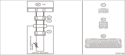
Wiring diagram:
CVT control system CVT Control System">

| STEP | CHECK | YES | NO |
1.CHECK HARNESS.
1) Turn the ignition switch to OFF.
2) Disconnect the TCM connector.
3) Measure the resistance of harness between TCM connector and chassis ground.
Connector & terminal
(B54) No. 1 — Chassis ground:
(B54) No. 6 — Chassis ground:
Is the resistance 1 M? or more?
Diagnostic Procedure with Diagnostic Trouble Code (DTC) > DTC P0712 TRANSMISSION FLUID TEMPERATURE SENSOR "A" CIRCUIT LOW">Go to Step 4.
Diagnostic Procedure with Diagnostic Trouble Code (DTC) > DTC P0712 TRANSMISSION FLUID TEMPERATURE SENSOR "A" CIRCUIT LOW">Go to Step 2.
2.CHECK HARNESS.
1) Disconnect the transmission connector.
2) Measure the resistance between transmission connector and transmission body.
Connector & terminal
(T4) No. 5 — Transmission body:
(T4) No. 9 — Transmission body:
Is the resistance 1 M? or more?
Repair the short circuit of body harness.
Diagnostic Procedure with Diagnostic Trouble Code (DTC) > DTC P0712 TRANSMISSION FLUID TEMPERATURE SENSOR "A" CIRCUIT LOW">Go to Step 3.
3.CHECK HARNESS INSIDE TRANSMISSION.
CAUTION:
Start work after ATF cools down.
1) Remove the transmission valve cover.
2) Check for the harness pinch, damage.
Is there any fault in the harness?
Replace the transmission harness.
Diagnostic Procedure with Diagnostic Trouble Code (DTC) > DTC P0712 TRANSMISSION FLUID TEMPERATURE SENSOR "A" CIRCUIT LOW">Go to Step 4.
4.CHECK ATF TEMPERATURE SENSOR.
Measure the resistance between transmission connector terminals.
Connector & terminal
(T11) No. 1 — No. 6:
NOTE:
Perform the measurements using multiple oil temperatures.
Is resistance as follows?
Fluid temperature 0°C > Approx. 6.0 k?
Fluid temperature 20°C > Approx. 2.5 k?
Fluid temperature 80°C > Approx. 330 ?
Replace the TCM. Transmission Control Module (TCM)">
Replace the control valve body. Control Valve Body">
1. OUTLINE OF DIAGNOSIS
• Detect the ground short circuit of transmission oil temperature sensor.
• Judge as NG if the voltage detected by the transmission oil temperature sensor is lower than the predetermined value.
2. EXECUTION CONDITION
Secondary Parameters | Execution condition |
12 V battery system voltage | ≥ 9 V |
3. DIAGNOSTIC METHOD
If the duration of time while the following conditions are met is longer than the time indicated, judge as NG.
Malfunction Criteria | Threshold Value |
Measured Transmission fluid temperature sensor input voltage | < 0.117 V |
(Transmission fluid temperature) | (> 146 degC) |
Time Needed for Diagnosis: 1 second
Malfunction Indicator Light Illumination: Illuminates as soon as a malfunction occurs.
 Dtc p0711 transmission fluid temperature sensor "a" circuit range/performance
CONTINUOUSLY VARIABLE TRANSMISSION (DIAGNOSTICS) > Diagnostic Procedure with Diagnostic Trouble Code (DTC)DTC P0711 TRANSMISSION FLUID TEMPERATURE SENSOR "A" CIRCUIT RANGE/PERFORMANCEDTC ...
 Dtc p0713 transmission fluid temperature sensor "a" circuit high
CONTINUOUSLY VARIABLE TRANSMISSION (DIAGNOSTICS) > Diagnostic Procedure with Diagnostic Trouble Code (DTC)DTC P0713 TRANSMISSION FLUID TEMPERATURE SENSOR "A" CIRCUIT HIGHDTC detecting con ...
Other materials:
If you park your vehicle in case of an emergency
Models with multi function display
Models without multi function display
The hazard warning flasher should be
used in day or night to warn other drivers
when you have to park your vehicle under
emergency conditions.
Avoid stopping on the road. It is best to
safely pull off the roa ...
Removal
POWER ASSISTED SYSTEM (POWER STEERING) > Electric Power Steering GearboxREMOVALCAUTION:• The power steering control module continues to operate after the engine stops and calculate the temperature in the control module. Therefore, before starting service of the power steering system which r ...
Dtc c2521 motor malfunction
POWER ASSISTED SYSTEM (POWER STEERING) (DIAGNOSTICS) > Diagnostic Procedure with Diagnostic Trouble Code (DTC)DTC C2521 MOTOR MALFUNCTIONTrouble symptom:• The steering wheel operation feels heavy.• STEERING warning light illuminates.Wiring diagram:Electric power steering system Elect ...
