Subaru Crosstrek Service Manual: Dtc p0516 battery temperature sensor circuit low
ENGINE (DIAGNOSTICS)(H4DO) > Diagnostic Procedure with Diagnostic Trouble Code (DTC)
DTC P0516 BATTERY TEMPERATURE SENSOR CIRCUIT LOW
DTC detecting condition:
Immediately at fault recognition
CAUTION:
After servicing or replacing faulty parts, perform Clear Memory Mode Clear Memory Mode > OPERATION"> , and Inspection Mode Inspection Mode > PROCEDURE">.
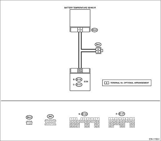
Wiring diagram:
Engine electrical system Engine Electrical System">
| STEP | CHECK | YES | NO |
1.CHECK CURRENT DATA.
1) Start the engine.
2) Read the value of «Battery temperature» using the Subaru Select Monitor.
NOTE:
For detailed operation procedures, refer to “Current Data Display For Engine”. Subaru Select Monitor">
Is the value of «Battery temperature» 100°C (212°F) or more?
Diagnostic Procedure with Diagnostic Trouble Code (DTC) > DTC P0516 BATTERY TEMPERATURE SENSOR CIRCUIT LOW">Go to Step 2.
Even if DTC is detected, the circuit has returned to a normal condition at this time. Reproduce the failure, and then perform the diagnosis again.
NOTE:
In this case, temporary poor contact of connector, temporary open or short circuit of harness may be the cause.
2.CHECK HARNESS BETWEEN ECM AND BATTERY TEMPERATURE SENSOR CONNECTOR.
1) Turn the ignition switch to OFF.
2) Disconnect the ECM connector.
3) Disconnect the connector from the battery temperature sensor.
4) Measure the resistance between ECM connector and chassis ground.
Connector & terminal
(B137) No. 24 — Chassis ground:
Is the resistance 1 M? or more?
Replace the battery temperature sensor. Battery Current & Temperature Sensor">
Repair the short circuit to ground in the harness between the ECM connector and battery temperature sensor connector.
1. OUTLINE OF DIAGNOSIS
Detect the open or short circuit of battery temperature sensor.
Judge as NG if out of specification.
2. COMPONENT DESCRIPTION
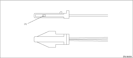
(1) | Sensor element |
3. EXECUTION CONDITION
Secondary Parameters | Execution condition |
Battery voltage | ≥ 10.9 V |
Elapsed time after starting the engine | > 1000 ms |
Engine speed | > 500 rpm |
Ignition switch | ON |
4. GENERAL DRIVING CYCLE
Always perform the diagnosis continuously.
5. DIAGNOSTIC METHOD
If the duration of time while the following conditions are met is longer than the time indicated, judge as NG.
Malfunction Criteria | Threshold Value |
Output voltage | < 0.1294 V |
Time Needed for Diagnosis: 500 ms
Malfunction Indicator Light Illumination: Does not illuminate even when malfunction occurs.
 Dtc p0852 park/neutral switch input circuit high
ENGINE (DIAGNOSTICS)(H4DO) > Diagnostic Procedure with Diagnostic Trouble Code (DTC)DTC P0852 PARK/NEUTRAL SWITCH INPUT CIRCUIT HIGH1. AT MODELDTC detecting condition:Detected when two consecutive ...
 Dtc p0517 battery temperature sensor circuit high
ENGINE (DIAGNOSTICS)(H4DO) > Diagnostic Procedure with Diagnostic Trouble Code (DTC)DTC P0517 BATTERY TEMPERATURE SENSOR CIRCUIT HIGHDTC detecting condition:Immediately at fault recognitionCAUTION: ...
Other materials:
Remote engine start system (dealer
option)
WARNING
There are some general precautions
when starting the engine.
Carefully read the precautions
described in "General precautions
when starting/stopping engine"
F7-9.
Do not remote start a vehicle in
an enclosed environment (e.g.
closed garage). Prolonged operation
of a mot ...
Dtc b28b9 eyesight steering switch 2
EyeSight (DIAGNOSTICS) > Diagnostic Procedure with Diagnostic Trouble Code (DTC)DTC B28B9 EyeSight STEERING SWITCH 2Detected when steering switch for EyeSight is not installed, is open-circuited or is stuck to ON.Refer to DTC B28B8 for diagnostic procedure. Diagnostic Procedure with Diagnostic T ...
Inspection
FUEL INJECTION (FUEL SYSTEMS)(H4DO) > Camshaft Position SensorINSPECTION1. CAMSHAFT POSITION SENSOR (METHOD WITH OSCILLOSCOPE)1. Prepare an oscilloscope.2. Remove the glove box. Glove Box > REMOVAL">3. Connect the probe to ECM connector.• Intake camshaft position sensor• E ...
