Subaru Crosstrek Service Manual: Dtc p014c a/f / o2 sensor slow response - rich to lean bank 1 sensor 1
ENGINE (DIAGNOSTICS)(H4DO) > Diagnostic Procedure with Diagnostic Trouble Code (DTC)
DTC P014C A/F / O2 SENSOR SLOW RESPONSE - RICH TO LEAN BANK 1 SENSOR 1
DTC DETECTING CONDITION:
Detected when two consecutive driving cycles with fault occur.
CAUTION:
After servicing or replacing faulty parts, perform Clear Memory Mode Clear Memory Mode > OPERATION"> , and Inspection Mode Inspection Mode > PROCEDURE">.
| STEP | CHECK | YES | NO |
1.CHECK EXHAUST SYSTEM.
NOTE:
Check the following items.
• Loose installation of front portion of exhaust pipe onto cylinder heads
• Loose connection between front exhaust pipe and front catalytic converter
• Damage of exhaust pipe resulting in a hole
Is there any fault in exhaust system?
Repair the exhaust system.
Replace the front oxygen (A/F) sensor. Front Oxygen (A/F) Sensor">
1. OUTLINE OF DIAGNOSIS
Detect the slow response of front oxygen (A/F) sensor.
For diagnosis, detect the trouble by processing the λ waveform in normal driving without forcibly changing the target air fuel ratio.
2. COMPONENT DESCRIPTION
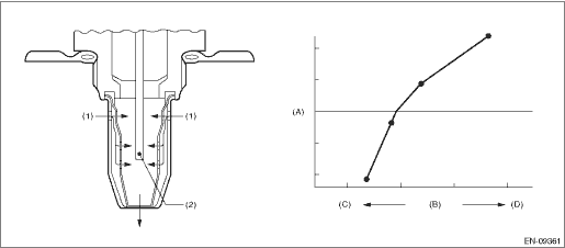
(A) | Electromotive force | (B) | Air fuel ratio | (C) | Rich |
(D) | Lean | ||||
(1) | Exhaust gas | (2) | Zirconia element oxygen |
3. EXECUTION CONDITION
Secondary parameters | Execution condition |
Battery voltage | ≥ 10.9 V |
Barometric pressure | ≥ 75.1 kPa (563 mmHg, 22.2 inHg) |
Duration of main feedback | ≥ 3000 ms |
Engine speed | ≥ 1000 rpm |
Amount of intake air | ≥ 10 g/s (0.35 oz/s) (CVT model) ≥ 10 g/s (0.35 oz/s) (MT model) |
4. GENERAL DRIVING CYCLE
Perform diagnosis only once in a city driving including normal acceleration and deceleration.
5. DIAGNOSTIC METHOD 1
Detect the malfunction by checking “Cumulative value of time when λ changes from lean > rich” in comparison to “Time during which diagnosis is in progress”.
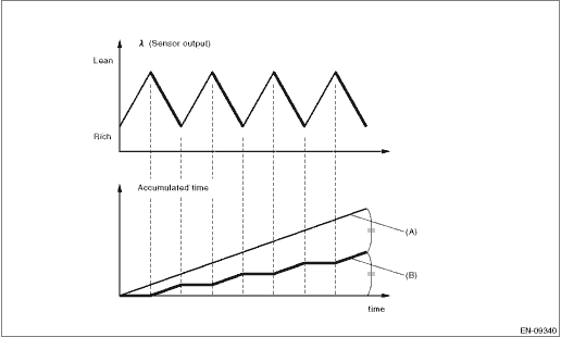
(A) | Time during which diagnosis is in progress | (B) | Cumulative value of time when λ changes from lean > rich |
Judge as NG when the following conditions are established.
Diagnosis (CVT model)
Malfunction Criteria | Threshold Value | DTC |
(Cumulative value of time when λ changes from lean > rich) / (Time during which diagnosis is in progress) | < 0.39 | P014C |
and | ||
Average value of time necessary for λ to inverse the air fuel ratio to Lean > Rich > Lean | < 30 ms | |
(Cumulative value of time when λ changes from rich > lean) / (Time during which diagnosis is in progress) | > 0.63 | P014D |
and | ||
Average value of time necessary for λ to inverse the air fuel ratio to Rich > Lean > Rich | > 20 ms |
Diagnosis (MT model)
Malfunction Criteria | Threshold Value | DTC |
(Cumulative value of time when λ changes from lean > rich) / (Time during which diagnosis is in progress) | < 0.4 | P014C |
and | ||
Average value of time necessary for λ to inverse the air fuel ratio to Lean > Rich > Lean | < 25 ms | |
(Cumulative value of time when λ changes from rich > lean) / (Time during which diagnosis is in progress) | > 0.6 | P014D |
and | ||
Average value of time necessary for λ to inverse the air fuel ratio to Rich > Lean > Rich | > 5 ms |
Diagnosis (CVT model)
Time Needed for Diagnosis: 90 seconds
Diagnosis (MT model)
Time Needed for Diagnosis: 60 seconds
Malfunction Indicator Light Illumination: Illuminates when malfunction occurs in 2 continuous driving cycles.
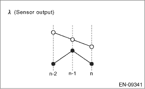
6. DIAGNOSTIC METHOD 2
Detect the malfunction by the cumulative value obtained from the amount of variation in λ change.
Judge as NG when the following conditions are established.
Malfunction Criteria | Threshold Value | DTC |
Cumulative value obtained from the amount of variation in λ change | < Value from Map | P014C and P014D |
Cumulative value obtained from the amount of variation in λ | 0.00 | 3.50 |
Cumulative value obtained from the amount of variation in λ change | 0.00 | 3.50 |
Cumulative value obtained from the amount of variation in λ | 0.00 | 3.50 |
Cumulative value obtained from the amount of variation in λ change | 0.00 | 3.50 |
Diagnosis (CVT model)
Time needed for diagnosis: 90 seconds
Diagnosis (MT model)
Time needed for diagnosis: 60 seconds
Malfunction indicator light illumination: Illuminates when malfunction occurs in 2 continuous driving cycles.
 Dtc p0141 o2 sensor heater circuit bank 1 sensor 2
ENGINE (DIAGNOSTICS)(H4DO) > Diagnostic Procedure with Diagnostic Trouble Code (DTC)DTC P0141 O2 SENSOR HEATER CIRCUIT BANK 1 SENSOR 2Refer to DTC P0037 for diagnostic procedure. Diagnostic Proced ...
 Dtc p014d a/f / o2 sensor slow response - lean to rich bank 1 sensor 1
ENGINE (DIAGNOSTICS)(H4DO) > Diagnostic Procedure with Diagnostic Trouble Code (DTC)DTC P014D A/F / O2 SENSOR SLOW RESPONSE - LEAN TO RICH BANK 1 SENSOR 1NOTE:For the diagnostic procedure, refer to ...
Other materials:
Installation
FRONT SUSPENSION > Front StrutINSTALLATION1. Install the strut mount - front at the upper side of the strut to the body, and tighten it with new flange nuts.Tightening torque:20 N·m (2.04 kgf-m, 14.8 ft-lb)2. Align alignment marks on the camber adjusting bolt and strut.Using new self-locki ...
Dtc c2521 motor malfunction
POWER ASSISTED SYSTEM (POWER STEERING) (DIAGNOSTICS) > Diagnostic Procedure with Diagnostic Trouble Code (DTC)DTC C2521 MOTOR MALFUNCTIONTrouble symptom:• The steering wheel operation feels heavy.• STEERING warning light illuminates.Wiring diagram:Electric power steering system Elect ...
Automatic Locking Retractor/Emergency Locking Retractor (ALR/ELR)
Each passenger's seatbelt has an Automatic
Locking Retractor/Emergency Locking
Retractor (ALR/ELR). The Automatic
Locking Retractor/Emergency Locking
Retractor normally functions as an Emergency
Locking Retractor (ELR). The ALR/
ELR has an additional locking mode
"Automatic Locking Retractor ...
