Subaru Crosstrek Service Manual: Dtc p013e o2 sensor delayed response - rich to lean bank 1 sensor 2
ENGINE (DIAGNOSTICS)(H4DO) > Diagnostic Procedure with Diagnostic Trouble Code (DTC)
DTC P013E O2 SENSOR DELAYED RESPONSE - RICH TO LEAN BANK 1 SENSOR 2
NOTE:
For the diagnostic procedure, refer to DTC P013A. Diagnostic Procedure with Diagnostic Trouble Code (DTC) > DTC P013A O2 SENSOR SLOW RESPONSE - RICH TO LEAN BANK 1 SENSOR 2">
1. OUTLINE OF DIAGNOSIS
Detect the delayed response of rear oxygen sensor output for rich > lean.
After the deceleration fuel cut has started, detect the trouble by calculating the time when the rear oxygen sensor output decreases to the predetermined voltages.
Judge as NG when the response time is larger than the threshold value.
2. COMPONENT DESCRIPTION
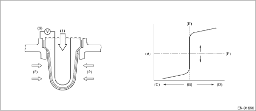
(A) | Electromotive force | (B) | Air fuel ratio | (C) | Lean |
(D) | Rich | (E) | Theoretical air fuel ratio | (F) | Comparative voltage |
(1) | Atmosphere | (2) | Exhaust gas | (3) | Electromotive force |
3. EXECUTION CONDITION
Secondary parameters | Execution condition |
Battery voltage | ≥ 10.9 V |
Rear oxygen sensor voltage when fuel cut starts | ≥ 0.55 V |
(Elapsed time after fuel cut | ≥ 5000 ms |
Fuel shut-off function from above) | Not in operation |
Rear oxygen sensor estimated element temperature when fuel cut starts | ≥ 500 °C (932 °F) |
4. GENERAL DRIVING CYCLE
Perform diagnosis once during deceleration fuel cut from a constant and high speed driving, when rear oxygen sensor is warmed up sufficiently.
5. DIAGNOSTIC METHOD
Detect the trouble by calculating the time from the beginning of the fuel cut to the beginning of the rear oxygen sensor voltage starting to drop.
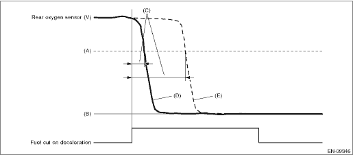
(A) | 0.5 V | (B) | 0 V | (C) | Diagnostic parameter |
(D) | Normal | (E) | Malfunction |
Judge as NG when the following conditions are established.
Malfunction Criteria | Threshold Value |
Time when rear oxygen sensor voltage changed to 0.5 V after the fuel cut started | > 4000 ms |
Time needed for diagnosis: Less than 1 second
Malfunction indicator light illumination: Illuminates when malfunction occurs in 2 continuous driving cycles.
 Dtc p013b o2 sensor slow response - lean to rich bank 1 sensor 2
ENGINE (DIAGNOSTICS)(H4DO) > Diagnostic Procedure with Diagnostic Trouble Code (DTC)DTC P013B O2 SENSOR SLOW RESPONSE - LEAN TO RICH BANK 1 SENSOR 2NOTE:For the diagnostic procedure, refer to DTC P ...
 Dtc p013f o2 sensor delayed response - lean to rich bank 1 sensor 2
ENGINE (DIAGNOSTICS)(H4DO) > Diagnostic Procedure with Diagnostic Trouble Code (DTC)DTC P013F O2 SENSOR DELAYED RESPONSE - LEAN TO RICH BANK 1 SENSOR 2NOTE:For the diagnostic procedure, refer to DT ...
Other materials:
Inspection
DRIVE SHAFT SYSTEM > Propeller ShaftINSPECTIONCheck the propeller shaft with the propeller shaft installed to the vehicle.1. Remove the front exhaust pipe. Front Exhaust Pipe > REMOVAL">2. Remove the center exhaust pipe, rear exhaust pipe, and muffler.• Center exhaust pipe & ...
14
CRUISE CONTROL SYSTEM (DIAGNOSTICS) > Diagnostic Procedure with Cancel Code14Detected when select lever is set in the neutral position, or when malfunction related to neutral position switch occurs.TROUBLE SYMPTOM:Cruise control cannot be set.WIRING DIAGRAM:Cruise control system Cruise Control S ...
Inspection
FUEL INJECTION (FUEL SYSTEMS)(H4DO) > Camshaft Position SensorINSPECTION1. CAMSHAFT POSITION SENSOR (METHOD WITH OSCILLOSCOPE)1. Prepare an oscilloscope.2. Remove the glove box. Glove Box > REMOVAL">3. Connect the probe to ECM connector.• Intake camshaft position sensor• E ...
