Subaru Crosstrek Service Manual: 14
CRUISE CONTROL SYSTEM (DIAGNOSTICS) > Diagnostic Procedure with Cancel Code
14
Detected when select lever is set in the neutral position, or when malfunction related to neutral position switch occurs.
TROUBLE SYMPTOM:
Cruise control cannot be set.
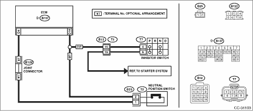
WIRING DIAGRAM:
Cruise control system Cruise Control System > WIRING DIAGRAM">
| STEP | CHECK | YES | NO |
1.CHECK TRANSMISSION TYPE.
Is the transmission type CVT?
Diagnostic Procedure with Cancel Code > 14">Go to Step 2.
Diagnostic Procedure with Cancel Code > 14">Go to Step 5. (MT model)
2.CHECK INHIBITOR SWITCH CIRCUIT.
1) Turn the ignition switch to OFF.
2) Disconnect the inhibitor switch harness connector.
3) Turn the ignition switch to ON.
4) Measure the voltage between harness connector terminal and chassis ground.
Connector & terminal
(T7) No. 6 (+) — Chassis ground (−):
Is the voltage 10 V or more?
Diagnostic Procedure with Cancel Code > 14">Go to Step 3.
Check for open or short in the harness between inhibitor switch and ECM.
3.CHECK INHIBITOR SWITCH CIRCUIT.
1) Turn the ignition switch to OFF.
2) Disconnect the starter motor harness connector.
3) Measure the resistance between inhibitor switch harness connector terminal and starter motor.
Connector & terminal
(T7) No. 9 — Starter motor:
Is the resistance less than 10 ??
Diagnostic Procedure with Cancel Code > 14">Go to Step 4.
Repair the harness.
4.CHECK INHIBITOR SWITCH.
Remove and check the inhibitor switch. Inhibitor Switch">
Is the inhibitor switch working normal?
Replace the ECM.
Engine Control Module (ECM)">
Replace the inhibitor switch.
5.CHECK NEUTRAL POSITION SWITCH CIRCUIT.
1) Turn the ignition switch to OFF.
2) Disconnect the neutral position switch harness connector.
3) Turn the ignition switch to ON.
4) Measure the voltage between harness connector terminal and chassis ground.
Connector & terminal
(B25) No. 2 (+) — Chassis ground (−):
Is the voltage 10 V or more?
Diagnostic Procedure with Cancel Code > 14">Go to Step 6.
Check for open or short in the harness between neutral position switch and ECM.
6.CHECK NEUTRAL POSITION SWITCH CIRCUIT.
1) Turn the ignition switch to OFF.
2) Measure resistance between harness connector terminal of neutral position switch and chassis ground.
Connector & terminal
(B25) No. 1 — Chassis ground:
Is the resistance less than 10 ??
Diagnostic Procedure with Cancel Code > 14">Go to Step 7.
Repair the harness.
7.CHECK NEUTRAL POSITION SWITCH.
Remove and check the neutral position switch. Neutral Position Switch">
Is the neutral position switch OK?
Replace the ECM.
Engine Control Module (ECM)">
Replace the neutral position switch.
 13
13
CRUISE CONTROL SYSTEM (DIAGNOSTICS) > Diagnostic Procedure with Cancel Code13Detected when clutch pedal is depressed or malfunction related to clutch switch occurs.TROUBLE SYMPTOM:• Cruise co ...
 15
15
CRUISE CONTROL SYSTEM (DIAGNOSTICS) > Diagnostic Procedure with Cancel Code15Detected when CANCEL switch is pressed or malfunction related to CRUISE switch occurs.TROUBLE SYMPTOM:• Cruise con ...
Other materials:
Dtc p0751 shift solenoid "a" performance/stuck off
CONTINUOUSLY VARIABLE TRANSMISSION (DIAGNOSTICS) > Diagnostic Procedure with Diagnostic Trouble Code (DTC)DTC P0751 SHIFT SOLENOID "A" PERFORMANCE/STUCK OFFDTC detecting condition:Detected when two consecutive driving cycles with fault occur.Trouble symptom:• Shift control malfunc ...
Installation
MANUAL TRANSMISSION AND DIFFERENTIAL(5MT) > Transfer Driven GearINSTALLATION1. Install the taper roller bearing (transfer case side) outer race.(A)Taper roller bearing (transfer case side) outer race(B)Transfer case2. Apply a coat of grease to the taper roller bearing (transfer case side) of tran ...
Caution
GLASS/WINDOWS/MIRRORS > General DescriptionCAUTION• Before disassembling or reassembling parts, always disconnect the battery ground cable from battery. When replacing the audio, control module and other parts provided with memory functions, record the memory contents before disconnecting t ...
