Subaru Crosstrek Service Manual: Dtc p0112 intake air temperature sensor 1 circuit low bank 1
ENGINE (DIAGNOSTICS)(H4DO) > Diagnostic Procedure with Diagnostic Trouble Code (DTC)
DTC P0112 INTAKE AIR TEMPERATURE SENSOR 1 CIRCUIT LOW BANK 1
DTC detecting condition:
Immediately at fault recognition
Trouble symptom:
• Improper idling
• Poor driving performance
CAUTION:
After servicing or replacing faulty parts, perform Clear Memory Mode Clear Memory Mode > OPERATION"> , and Inspection Mode Inspection Mode > PROCEDURE">.
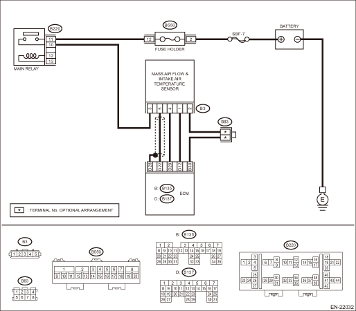
Wiring diagram:
Engine electrical system Engine Electrical System">
| STEP | CHECK | YES | NO |
1.CHECK CURRENT DATA.
1) Start the engine.
2) Read the value of «Intake Air Temp.» using the Subaru Select Monitor or a general scan tool.
NOTE:
• Subaru Select Monitor
For detailed operation procedures, refer to “Current Data Display For Engine”. Subaru Select Monitor">
• General scan tool
For detailed operation procedures, refer to the general scan tool operation manual.
Is the value of «Intake Air Temp.» 120°C (248°F) or more?
Diagnostic Procedure with Diagnostic Trouble Code (DTC) > DTC P0112 INTAKE AIR TEMPERATURE SENSOR 1 CIRCUIT LOW BANK 1">Go to Step 2.
Even if DTC is detected, the circuit has returned to a normal condition at this time. Reproduce the failure, and then perform the diagnosis again.
NOTE:
In this case, temporary poor contact of connector, temporary open or short circuit of harness may be the cause.
2.CHECK HARNESS BETWEEN ECM AND MASS AIR FLOW AND INTAKE AIR TEMPERATURE SENSOR CONNECTOR.
1) Turn the ignition switch to OFF.
2) Disconnect the connector from ECM.
3) Disconnect the connectors from the mass air flow and intake air temperature sensor.
4) Measure the resistance between ECM connector and chassis ground.
Connector & terminal
(B137) No. 12 — Chassis ground:
Is the resistance 1 M? or more?
Replace the mass air flow and intake air temperature sensor. Mass Air Flow and Intake Air Temperature Sensor">
Repair the ground short circuit of harness between ECM connector and the mass air flow and intake air temperature sensor connector.
1. OUTLINE OF DIAGNOSIS
Detect open or short circuit of the intake air temperature sensor.
Judge as NG if out of specification.
2. COMPONENT DESCRIPTION
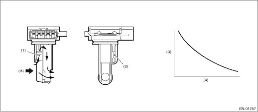
(A) | Air | ||||
(1) | Air flow sensor | (3) | Resistance value (?) | (4) | Intake air temperature °C (°F) |
(2) | Intake air temperature sensor |
3. EXECUTION CONDITION
Secondary Parameters | Execution condition |
None |
4. GENERAL DRIVING CYCLE
Always perform the diagnosis continuously.
5. DIAGNOSTIC METHOD
If the duration of time while the following conditions are met is longer than the time indicated, judge as NG.
Malfunction Criteria | Threshold Value |
Output voltage | < 0.4 V |
Time Needed for Diagnosis: 500 ms
Malfunction Indicator Light Illumination: Illuminates as soon as a malfunction occurs.
 Dtc p0111 intake air temperature sensor 1 circuit range/performance bank 1
ENGINE (DIAGNOSTICS)(H4DO) > Diagnostic Procedure with Diagnostic Trouble Code (DTC)DTC P0111 INTAKE AIR TEMPERATURE SENSOR 1 CIRCUIT RANGE/PERFORMANCE BANK 1DTC detecting condition:Detected when t ...
 Dtc p0113 intake air temperature sensor 1 circuit high bank 1
ENGINE (DIAGNOSTICS)(H4DO) > Diagnostic Procedure with Diagnostic Trouble Code (DTC)DTC P0113 INTAKE AIR TEMPERATURE SENSOR 1 CIRCUIT HIGH BANK 1DTC detecting condition:Immediately at fault recogni ...
Other materials:
Fuel pump circuit
ENGINE (DIAGNOSTICS)(H4DO) > Diagnostics for Engine Starting FailureFUEL PUMP CIRCUITCAUTION:After servicing or replacing faulty parts, perform Clear Memory Mode Clear Memory Mode > OPERATION">, and Inspection Mode Inspection Mode > PROCEDURE">.Wiring diagram:Engine electr ...
Removal
SEAT BELT SYSTEM > Rear Seat BeltREMOVAL1. SEAT BELT OUTER - REAR RH & LHCAUTION:• Airbag system satellite safing sensor is located in the lower of the rear seat cushion center. Be careful not to apply strong impact to the sensor when working with the rear seat cushion removed.• B ...
Installation
LIGHTING SYSTEM > Combination Switch (Light)INSTALLATIONCAUTION:• Before handling the airbag system components, refer to “CAUTION” of “General Description” in “AIRBAG SYSTEM”. General Description > CAUTION">• Do not allow harness and con ...
