Subaru Crosstrek Service Manual: Dtc p0071 ambient air temperature sensor circuit "a" range/performance
ENGINE (DIAGNOSTICS)(H4DO) > Diagnostic Procedure with Diagnostic Trouble Code (DTC)
DTC P0071 AMBIENT AIR TEMPERATURE SENSOR CIRCUIT "A" RANGE/PERFORMANCE
DTC detecting condition:
Detected when two consecutive driving cycles with fault occur.
CAUTION:
After servicing or replacing faulty parts, perform Clear Memory Mode Clear Memory Mode > OPERATION"> , and Inspection Mode Inspection Mode > PROCEDURE">.
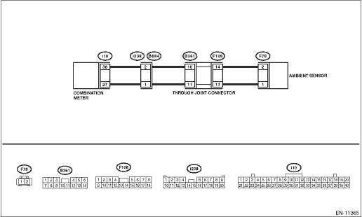
Wiring diagram:
Air conditioning system Air Conditioning System > WIRING DIAGRAM">
| STEP | CHECK | YES | NO |
1.CHECK FOR ANY OTHER DTC ON DISPLAY.
Is any other DTC displayed?
Check the appropriate DTC using the “List of Diagnostic Trouble Code (DTC)”. List of Diagnostic Trouble Code (DTC)">
Diagnostic Procedure with Diagnostic Trouble Code (DTC) > DTC P0071 AMBIENT AIR TEMPERATURE SENSOR CIRCUIT "A" RANGE/PERFORMANCE">Go to Step 2.
2.CHECK AMBIENT SENSOR.
1) Turn the ignition switch to OFF.
2) Disconnect the connector from ambient sensor.
3) Measure the resistance between ambient sensor terminals while heating and cooling the ambient sensor using a hair dryer.
CAUTION:
Do not heat the part to the temperature where you cannot touch it with your bare hand in order to prevent burning yourself and protect the part.
Terminals
No. 1 — No. 2:
Does the resistance value of ambient sensor change between heating and cooling?
Repair the poor contact of ECM connector.
Replace the ambient sensor. Ambient Sensor">
1. OUTLINE OF DIAGNOSIS
Detect the malfunction of ambient temperature sensor characteristics.
After the engine starts after the specified period of soaking time has elapsed, judge by correlation between ambient temperature sensor value, intake air temperature sensor value and engine coolant temperature sensor value. Judge as NG when the differences are both above the specified value by comparing between ambient air temperature and intake air temperature, ambient air temperature and engine coolant temperature.
2. COMPONENT DESCRIPTION
Ambient temperature sensor is connected to combination meter. ECM receives the data of ambient temperature sensor via CAN communication with combination meter.
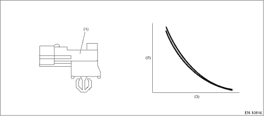
(1) | Ambient sensor | (2) | Resistance value (k?) | (3) | Ambient air temperature (°C (°F)) |
3. EXECUTION CONDITION
Secondary parameters | Execution condition |
Battery voltage | ≥ 10.9 V |
Soaking time | ≥ 21600 s |
Block heater judgment | Completed |
Block heater operation | Not in operation |
4. GENERAL DRIVING CYCLE
Perform the diagnosis only once after the engine starts after a certain period of soaking time.
5. DIAGNOSTIC METHOD
If the duration of time while the following conditions are met is longer than the time indicated, judge as NG.
Malfunction Criteria | Threshold Value |
|Ambient air temperature 30 sec. after engine start − Intake air temperature 30 sec. after engine start| | > Value from Map |
|Ambient air temperature at engine start − Engine coolant temperature at engine start| | > 25 °C (45°F) |
Ambient temperature °C (°F) | −30 (−22) | 45 (113) | 60 (140) | 80 (176) |
|Ambient air temperature 30 sec. after engine start − Intake air temperature 30 sec. after engine start| °C (°F) | 20 (36°F) | 20 (36°F) | 32 (57.6°F) | 32 (57.6°F) |
Time needed for diagnosis: Less than 1 second
Malfunction indicator light illumination: Illuminates when malfunction occurs in 2 continuous driving cycles.
 Dtc p0068 map/maf - throttle position correlation
ENGINE (DIAGNOSTICS)(H4DO) > Diagnostic Procedure with Diagnostic Trouble Code (DTC)DTC P0068 MAP/MAF - THROTTLE POSITION CORRELATIONDTC detecting condition:Detected when two consecutive driving cy ...
 Dtc p0072 ambient air temperature sensor circuit "a" low
ENGINE (DIAGNOSTICS)(H4DO) > Diagnostic Procedure with Diagnostic Trouble Code (DTC)DTC P0072 AMBIENT AIR TEMPERATURE SENSOR CIRCUIT "A" LOWDTC detecting condition:Immediately at fault re ...
Other materials:
Dtc b2313 rear radar detect vdc
Blind Spot Detection/Rear Cross Traffic Alert (DIAGNOSTICS) > Diagnostic Procedure with Diagnostic Trouble Code (DTC)DTC B2313 REAR RADAR DETECT VDCDTC DETECTING CONDITION:Vehicle dynamics control (VDC) fails.TROUBLE SYMPTOM:• All functions of BSD/RCTA stop.• Fail icon is displayed in ...
Dtc b1635 curtain airbag sensor lh failure
AIRBAG SYSTEM (DIAGNOSTICS) > Diagnostic Chart with Trouble CodeDTC B1635 CURTAIN AIRBAG SENSOR LH FAILUREDIAGNOSIS START CONDITION:Ignition voltage is 10 V to 16 V.DTC DETECTING CONDITION:Curtain airbag sensor (LH) is faulty.If DTC B1635 is displayed, the circuit within the curtain airbag sensor ...
Component
EXTERIOR/INTERIOR TRIM > General DescriptionCOMPONENT1. FRONT UNDER COVER(1)Under cover - front(3)Spacer - under coverTightening torque: N·m (kgf-m, ft-lb)(2)Mud guard - front T:18 (1.84, 13.3)2. MUD GUARD(1)Under cover - front(2)Mud guard - front(3)Mud guard - rear3. FLOOR UNDER PROTECTO ...
