Subaru Crosstrek Service Manual: Dtc c1413 power supply voltage
VEHICLE DYNAMICS CONTROL (VDC) (DIAGNOSTICS) > Diagnostic Procedure with Diagnostic Trouble Code (DTC)
DTC C1413 POWER SUPPLY VOLTAGE
DTC detecting condition:
Improper VDCCM&H/U power supply voltage
Trouble symptom:
• ABS does not operate.
• EBD may not operate.
• VDC does not operate.
• Hill start assist does not operate.
NOTE:
Warning lights go off if voltage returns.
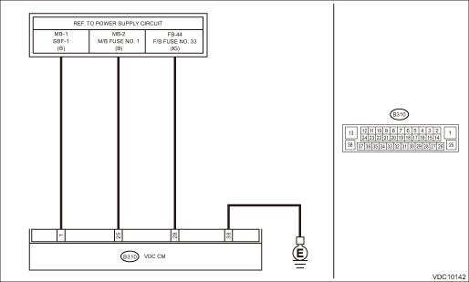
Wiring diagram:
Vehicle dynamics control system Vehicle Dynamics Control System > WIRING DIAGRAM">
| STEP | CHECK | YES | NO |
1.CHECK GENERATOR.
1) Start the engine.
2) Run the engine at idle after warming up.
3) Measure the voltage between generator terminal B and chassis ground.
Terminals
Generator terminal B (+) — Chassis ground (−):
Is the voltage 10 — 15 V?
Diagnostic Procedure with Diagnostic Trouble Code (DTC) > DTC C1413 POWER SUPPLY VOLTAGE">Go to Step 2.
Repair the generator.
2.CHECK BATTERY TERMINAL.
Turn the ignition switch to OFF.
Are the positive and negative battery terminals clamped tightly?
Diagnostic Procedure with Diagnostic Trouble Code (DTC) > DTC C1413 POWER SUPPLY VOLTAGE">Go to Step 3.
Install the battery terminal correctly.
3.CHECK VDCCM&H/U INPUT VOLTAGE.
1) Disconnect the connector from the VDCCM&H/U.
2) Run the engine at idle.
3) Operate devices such as headlights, air conditioner, rear defogger, etc. which produce an electrical load.
4) Measure the voltage between VDCCM&H/U connector and chassis ground.
Connector & terminal
(B310) No. 1 (+) — Chassis ground (−):
(B310) No. 25 (+) — Chassis ground (−):
(B310) No. 28 (+) — Chassis ground (−):
Is the voltage 10 — 15 V?
Diagnostic Procedure with Diagnostic Trouble Code (DTC) > DTC C1413 POWER SUPPLY VOLTAGE">Go to Step 4.
Repair the power supply circuit.
4.CHECK VDCCM&H/U GROUND CIRCUIT (CHECK FOR OPEN CIRCUIT).
1) Turn the ignition switch to OFF.
2) Measure the resistance between VDCCM&H/U connector and chassis ground.
Connector & terminal
(B310) No. 38 — Chassis ground:
Is the resistance less than 10 ??
Diagnostic Procedure with Diagnostic Trouble Code (DTC) > DTC C1413 POWER SUPPLY VOLTAGE">Go to Step 5.
Repair the VDCCM&H/U ground harness.
5.CHECK POOR CONTACT OF CONNECTORS.
Is there poor contact of connector between generator, battery and VDCCM&H/U?
Repair the connector.
Diagnostic Procedure with Diagnostic Trouble Code (DTC) > DTC C1413 POWER SUPPLY VOLTAGE">Go to Step 6.
6.CHECK VDCCM&H/U.
1) Connect all connectors.
2) Perform the Clear Memory Mode. Clear Memory Mode">
3) Perform the Inspection Mode. Inspection Mode">
4) Read the DTC. Read Diagnostic Trouble Code (DTC)">
Is the same DTC displayed?
Replace the VDCCM only. VDC Control Module and Hydraulic Control Unit (VDCCM&H/U) > REPLACEMENT">
Diagnostic Procedure with Diagnostic Trouble Code (DTC) > DTC C1413 POWER SUPPLY VOLTAGE">Go to Step 7.
7.CHECK DETECTION OF OTHER DTCS FOR VDC.
Read Diagnostic Trouble Code (DTC)">
Is any other DTC displayed?
Perform the diagnosis according to DTC. List of Diagnostic Trouble Code (DTC)">
Currently, it is normal. There may have been a temporary poor contact in the harness and connector or a temporary noise interference.
 Dtc c1412 selected parameter
VEHICLE DYNAMICS CONTROL (VDC) (DIAGNOSTICS) > Diagnostic Procedure with Diagnostic Trouble Code (DTC)DTC C1412 SELECTED PARAMETERDTC DETECTING CONDITION:VDCCM parameter selection errorTROUBLE SYMP ...
 Dtc c1424 ecm
VEHICLE DYNAMICS CONTROL (VDC) (DIAGNOSTICS) > Diagnostic Procedure with Diagnostic Trouble Code (DTC)DTC C1424 ECMDTC detecting condition:ECM malfunctioningTrouble symptom:• ABS does not ope ...
Other materials:
Installation
VEHICLE DYNAMICS CONTROL (VDC) > VDC Control Module and Hydraulic Control Unit (VDCCM&H/U)INSTALLATION1. MODELS WITHOUT EyeSightCAUTION:• When installing the VDCCM&H/U to the bracket - hydraulic unit, make sure that there is no oil adhered to the bolts and the threads of VDCCM&H ...
BSD/RCTA warning indicator
System malfunction
BSD/RCTA malfunction message
At first, this message will appear
Then this message will appear
BSD/RCTA warning indicator
If a malfunction occurs within the BSD/RCTA system of the Subaru Ascent, a sequence
of warning messages will be displayed followed by the act ...
Removal
LIGHTING SYSTEM > License Plate LightREMOVAL1. Disconnect the ground cable from battery. NOTE">2. Remove the license plate light.(1) Release the claws and pull out the license plate light.(2) Disconnect the connector and remove the bulb socket and bulb from the license plate light.CAUTIO ...
