Subaru Crosstrek Service Manual: Dtc c0071 no signal from steering angle sensor
VEHICLE DYNAMICS CONTROL (VDC) (DIAGNOSTICS) > Diagnostic Procedure with Diagnostic Trouble Code (DTC)
DTC C0071 NO SIGNAL FROM STEERING ANGLE SENSOR
DTC detecting condition:
Communication from steering angle sensor is faulty.
Trouble symptom:
• VDC does not operate.
• EyeSight does not operate.
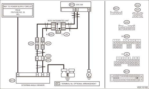
Wiring diagram:
Vehicle dynamics control system Vehicle Dynamics Control System > WIRING DIAGRAM">
| STEP | CHECK | YES | NO |
1.CHECK POWER SUPPLY FOR STEERING ANGLE SENSOR.
1) Turn the ignition switch to OFF.
2) Disconnect the connector from steering angle sensor.
3) Turn the ignition switch to ON.
4) Measure the voltage between steering angle sensor and chassis ground.
Connector & terminal
(B231) No. 4 (+) — Chassis ground (−):
Is the voltage 10 — 15 V?
Diagnostic Procedure with Diagnostic Trouble Code (DTC) > DTC C0071 NO SIGNAL FROM STEERING ANGLE SENSOR">Go to Step 2.
Repair the steering angle sensor power supply circuit.
2.CHECK GROUND CIRCUIT OF STEERING ANGLE SENSOR (CHECK FOR OPEN CIRCUIT).
Measure the resistance between steering angle sensor and chassis ground.
Connector & terminal
(B231) No. 1 — Chassis ground:
Is the resistance less than 10 ??
Diagnostic Procedure with Diagnostic Trouble Code (DTC) > DTC C0071 NO SIGNAL FROM STEERING ANGLE SENSOR">Go to Step 3.
Repair ground circuit in the steering angle sensor.
3.CHECK VDCCM&H/U.
1) Turn the ignition switch to OFF.
2) Connect all connectors.
3) Perform the Clear Memory Mode. Clear Memory Mode">
4) Perform the Inspection Mode. Inspection Mode">
5) Read the DTC. Read Diagnostic Trouble Code (DTC)">
Is the same DTC displayed?
Diagnostic Procedure with Diagnostic Trouble Code (DTC) > DTC C0071 NO SIGNAL FROM STEERING ANGLE SENSOR">Go to Step 4.
Diagnostic Procedure with Diagnostic Trouble Code (DTC) > DTC C0071 NO SIGNAL FROM STEERING ANGLE SENSOR">Go to Step 5.
4.CHECK VDCCM&H/U.
1) Turn the ignition switch to OFF.
2) Replace the steering angle sensor. Steering Angle Sensor">
3) Perform the Clear Memory Mode. Clear Memory Mode">
4) Perform the Inspection Mode. Inspection Mode">
5) Read the DTC. Read Diagnostic Trouble Code (DTC)">
Is the same DTC displayed?
Replace the VDCCM&H/U. VDC Control Module and Hydraulic Control Unit (VDCCM&H/U)">
Diagnostic Procedure with Diagnostic Trouble Code (DTC) > DTC C0071 NO SIGNAL FROM STEERING ANGLE SENSOR">Go to Step 6.
5.CHECK DETECTION OF OTHER DTCS FOR VDC.
Read Diagnostic Trouble Code (DTC)">
Is any other DTC displayed?
Perform the diagnosis according to DTC. List of Diagnostic Trouble Code (DTC)">
Currently, it is normal. There may have been a temporary poor contact in the harness and connector or a temporary noise interference.
6.CHECK DETECTION OF OTHER DTCS FOR VDC.
Read Diagnostic Trouble Code (DTC)">
Is any other DTC displayed?
Perform the diagnosis according to DTC. List of Diagnostic Trouble Code (DTC)">
Original steering angle sensor malfunction
 Dtc c0057 vdc interrupted due to egi reason
VEHICLE DYNAMICS CONTROL (VDC) (DIAGNOSTICS) > Diagnostic Procedure with Diagnostic Trouble Code (DTC)DTC C0057 VDC INTERRUPTED DUE TO EGI REASONDTC DETECTING CONDITION:Cooperation control prohibit ...
 Dtc c0074 master cylinder pressure sensor output
VEHICLE DYNAMICS CONTROL (VDC) (DIAGNOSTICS) > Diagnostic Procedure with Diagnostic Trouble Code (DTC)DTC C0074 MASTER CYLINDER PRESSURE SENSOR OUTPUTDTC detecting condition:Defective pressure sens ...
Other materials:
Dtc u0140 lost communication with body control module
INSTRUMENTATION/DRIVER INFO (DIAGNOSTICS) > Diagnostic Procedure with Diagnostic Trouble Code (DTC)DTC U0140 LOST COMMUNICATION WITH BODY CONTROL MODULEDetected when CAN data is not received from body integrated unit.NOTE:Perform the diagnosis for LAN system. Basic Diagnostic Procedure > PROC ...
Welcome screen and Good-bye screen
When the driver's door is opened and
closed after unlocking the door, the
welcome screen will appear on the multi
information display for approximately 20
seconds.
When the ignition switch is turned to the
"LOCK"/"OFF" position, the multi information
display gradually turns off (Good-bye
s ...
Double trip meter
Type A
Trip knob
Type B
Trip knob (U.S.-spec. models)
Trip knob (except U.S.-spec. models)
This meter displays the two trip meters
when the ignition switch is in the "ON"
position.
The trip meter shows the distance that the
vehicle has been driven since you last set
it to ...
