Subaru Crosstrek Service Manual: Dtc b2a08 sos button circuit
TELEMATICS SYSTEM (DIAGNOSTICS) > Diagnostic Procedure with Diagnostic Trouble Code (DTC)
DTC B2A08 SOS BUTTON CIRCUIT
Diagnosis start condition:
When ignition switch is ON.
DTC detecting condition:
The following conditions occur for at least 50 ms.
• SOS button impedance is more than 10 k?.
• SOS button is stuck for at least 60 seconds.
Trouble symptom:
• SOS function cannot be used.
• RED LED illuminates.
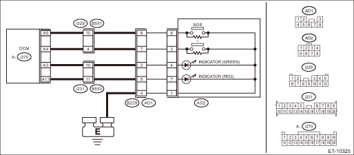
Wiring diagram:
NOTE:
For the coupling connector, refer to “WIRING SYSTEM”.
Telematics Telematics System > WIRING DIAGRAM">
CAUTION:
CommCheck is required after replacing the DCM. Telematics System > OPERATION">
| STEP | CHECK | YES | NO |
1.CHECK DTC.
Read the DTC. Diagnostic Code(s) Display">
Is DTC B2A08 displayed? (Current malfunction)
Diagnostic Procedure with Diagnostic Trouble Code (DTC) > DTC B2A08 SOS BUTTON CIRCUIT">Go to Step 2.
Even if DTC is displayed, the circuit has returned to a normal condition at this time. Reproduce the failure, and then perform the diagnosis again.
In this case, temporary poor contact of connector, temporary open or short circuit of harness may be the cause.
2.CHECK HARNESS (OPEN CIRCUIT).
1) Turn the ignition switch to OFF.
2) Disconnect the telematics button connector.
3) Disconnect the DCM connector.
4) Measure the resistance between telematics button connector and DCM connector.
Connector & terminal
(i270) No. 5 — (AD2) No. 6:
(AD2) No. 1 — Chassis ground:
Is the resistance 1 ? or less?
Diagnostic Procedure with Diagnostic Trouble Code (DTC) > DTC B2A08 SOS BUTTON CIRCUIT">Go to Step 3.
Repair or replace the open circuit of harness.
3.CHECK HARNESS (GROUND SHORT CIRCUIT).
Measure the resistance between DCM connector and chassis ground.
Connector & terminal
(i270) No. 5 — Chassis ground:
Is the resistance 1 M? or more?
Diagnostic Procedure with Diagnostic Trouble Code (DTC) > DTC B2A08 SOS BUTTON CIRCUIT">Go to Step 4.
Repair or replace the short circuit of the harness.
4.CHECK THE CONNECTOR (SHORT CIRCUIT TO POWER SUPPLY).
Measure the voltage between DCM connector and chassis ground.
Connector & terminal
(i270) No. 5 (+) — Chassis ground (−):
(AD2) No. 1 (+) — Chassis ground (−):
Is the voltage less than 1 V?
Diagnostic Procedure with Diagnostic Trouble Code (DTC) > DTC B2A08 SOS BUTTON CIRCUIT">Go to Step 5.
Repair or replace the short circuit of the harness.
5.CHECK THE SOS BUTTON UNIT.
Measure the resistance of the SOS button unit.
Terminals
No. 6 — No. 1:
Is the resistance 1 ? or less when SOS button is ON, and 1.6 (±5%) k? or more when SOS button is OFF?
Replace the DCM. Data Communication Module">
Replace the telematics button. Switches and Harness">
 Dtc b2a06 right speaker/audio circuit
TELEMATICS SYSTEM (DIAGNOSTICS) > Diagnostic Procedure with Diagnostic Trouble Code (DTC)DTC B2A06 RIGHT SPEAKER/AUDIO CIRCUITDiagnosis start condition:When ACC is ON.DTC detecting condition:Speake ...
 Dtc b2a09 i-call button circuit
TELEMATICS SYSTEM (DIAGNOSTICS) > Diagnostic Procedure with Diagnostic Trouble Code (DTC)DTC B2A09 I-CALL BUTTON CIRCUITDiagnosis start condition:When ignition switch is ON.DTC detecting condition: ...
Other materials:
Installation
EXTERIOR BODY PANELS > Front FenderINSTALLATION1. Install each part in the reverse order of removal.CAUTION:• Install the bumper face - front so that the front end of the under cover (b) comes inside the bumper face - front (a), and the front end of the mud guard (c) comes outside the bumpe ...
Dtc p0108 manifold absolute pressure/barometric pressure sensor circuit high
ENGINE (DIAGNOSTICS)(H4DO) > Diagnostic Procedure with Diagnostic Trouble Code (DTC)DTC P0108 MANIFOLD ABSOLUTE PRESSURE/BAROMETRIC PRESSURE SENSOR CIRCUIT HIGHDTC detecting condition:Immediately at fault recognitionCAUTION:After servicing or replacing faulty parts, perform Clear Memory Mode Cle ...
Adjustment
AIRBAG SYSTEM > Roll ConnectorADJUSTMENTCAUTION:• Do not rotate the roll connector to more than the specified number of turns. Otherwise, the roll connector internal wire may be broken.• When determining the end stop, rotate the connector slowly without applying excessive force. Apply ...
