Subaru Crosstrek Service Manual: Dtc b2a05 left speaker/audio circuit
TELEMATICS SYSTEM (DIAGNOSTICS) > Diagnostic Procedure with Diagnostic Trouble Code (DTC)
DTC B2A05 LEFT SPEAKER/AUDIO CIRCUIT
Diagnosis start condition:
When ACC is ON.
DTC detecting condition:
Speaker impedance is more than 10 k? for 100 ms. (Detached speaker connection, etc.)
Trouble symptom:
• Call function cannot be used.
• RED LED illuminates.
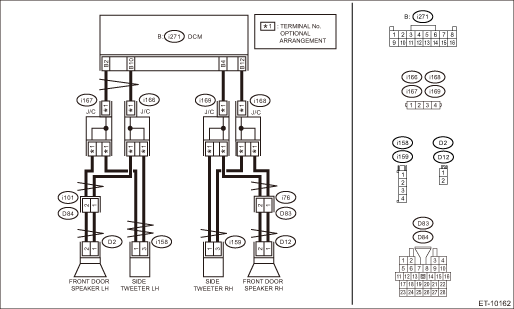
Wiring diagram:
NOTE:
For the coupling connector, refer to “WIRING SYSTEM”.
Telematics Telematics System > WIRING DIAGRAM">
CAUTION:
CommCheck is required after replacing the DCM. Telematics System > OPERATION">
| STEP | CHECK | YES | NO |
1.CHECK DTC.
Read the DTC. Diagnostic Code(s) Display">
Is DTC B2A05 displayed? (Current malfunction)
Diagnostic Procedure with Diagnostic Trouble Code (DTC) > DTC B2A05 LEFT SPEAKER/AUDIO CIRCUIT">Go to Step 2.
Even if DTC is displayed, the circuit has returned to a normal condition at this time. Reproduce the failure, and then perform the diagnosis again.
In this case, temporary poor contact of connector, temporary open or short circuit of harness may be the cause.
2.PERFORM THE SYSTEM OPERATION CHECK.
Perform [Speaker ON] in the system operation check mode. System Operation Check Mode">
Does it sound?
Even if DTC is displayed, the circuit has returned to a normal condition at this time. Reproduce the failure, and then perform the diagnosis again.
In this case, temporary poor contact of connector, temporary open or short circuit of harness may be the cause.
Diagnostic Procedure with Diagnostic Trouble Code (DTC) > DTC B2A05 LEFT SPEAKER/AUDIO CIRCUIT">Go to Step 3.
3.CHECK HARNESS (OPEN CIRCUIT).
1) Turn the ignition switch to OFF.
2) Disconnect the speaker connector and tweeter connector.
3) Disconnect the DCM connector.
4) Measure the resistance between speaker connector and tweeter connector and DCM connector.
Connector & terminal
(i271) No. 2 — (D2) No. 2:
(i271) No. 2 — (i158) No. 1:
(i271) No. 10 — (D2) No. 1:
(i271) No. 10 — (i158) No. 3:
Is the resistance 1 ? or less?
Diagnostic Procedure with Diagnostic Trouble Code (DTC) > DTC B2A05 LEFT SPEAKER/AUDIO CIRCUIT">Go to Step 4.
Repair or replace the open circuit of harness.
4.CHECK HARNESS (GROUND SHORT CIRCUIT).
Measure the resistance between DCM connector and chassis ground.
Connector & terminal
(i271) No. 2 — Chassis ground:
(i271) No. 10 — Chassis ground:
Is the resistance 1 M? or more?
Diagnostic Procedure with Diagnostic Trouble Code (DTC) > DTC B2A05 LEFT SPEAKER/AUDIO CIRCUIT">Go to Step 5.
Repair or replace the short circuit of the harness.
5.CHECK THE CONNECTOR (SHORT CIRCUIT TO POWER SUPPLY).
Measure the voltage between DCM connector and chassis ground.
Connector & terminal
(i271) No. 2 (+) — Chassis ground (−):
(i271) No. 10 (+) — Chassis ground (−):
Is the voltage less than 1 V?
Diagnostic Procedure with Diagnostic Trouble Code (DTC) > DTC B2A05 LEFT SPEAKER/AUDIO CIRCUIT">Go to Step 6.
Repair or replace the short circuit of the harness.
6.CHECK THE SPEAKER.
Perform the inspection of speaker unit and tweeter unit. Front Speaker"> Rear Speaker">
Are the speaker and tweeter OK?
Replace the DCM. Data Communication Module">
Replace the speaker and tweeter. Front Speaker"> Rear Speaker">
 Dtc b2a04 mic circuit
TELEMATICS SYSTEM (DIAGNOSTICS) > Diagnostic Procedure with Diagnostic Trouble Code (DTC)DTC B2A04 MIC CIRCUITDiagnosis start condition:When ACC is ON.DTC detecting condition:Any of the followings ...
 Dtc b2a06 right speaker/audio circuit
TELEMATICS SYSTEM (DIAGNOSTICS) > Diagnostic Procedure with Diagnostic Trouble Code (DTC)DTC B2A06 RIGHT SPEAKER/AUDIO CIRCUITDiagnosis start condition:When ACC is ON.DTC detecting condition:Speake ...
Other materials:
Except U.S.-spec. models (type B)
The illustration above is a typical example. For some models, the combination
meter
may be slightly different than that shown in the illustration.
Tachometer
Multi information display
Fuel gauge
Select lever/gear position indicator
Speedometer
Trip meter A/B selection and trip m ...
Dtc b14a1 sunload sensor circuit low/open
HVAC SYSTEM (AUTO A/C) (DIAGNOSTICS) > Diagnostic Procedure with Diagnostic Trouble Code (DTC)DTC B14A1 SUNLOAD SENSOR CIRCUIT LOW/OPENDTC detecting condition:Sunload sensor circuit is open. (Displayed for current malfunction)NOTE:When the sunload sensor check is performed indoors or in the shade ...
Dtc b1013 ignition power
BODY CONTROL SYSTEM (DIAGNOSTICS) > Diagnostic Procedure with Diagnostic Trouble Code (DTC)DTC B1013 IGNITION POWERDTC detecting condition:Voltage failure caused by poor contact of IGN power supply circuitsTrouble symptom:Symptoms such as shift lock or wiper not operating may occur.Wiring diagram ...
