Subaru Crosstrek Service Manual: Dtc b2a04 mic circuit
TELEMATICS SYSTEM (DIAGNOSTICS) > Diagnostic Procedure with Diagnostic Trouble Code (DTC)
DTC B2A04 MIC CIRCUIT
Diagnosis start condition:
When ACC is ON.
DTC detecting condition:
Any of the followings continues for 1 second or more.
• MIC impedance is more than 10 k?. (Detached MIC, etc.)
• MIC impedance is less than 10 ?. (Short-circuited MIC, etc.)
Trouble symptom:
• Call function cannot be used.
• RED LED illuminates.
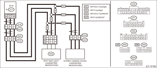
Wiring diagram:
NOTE:
For the coupling connector, refer to “WIRING SYSTEM”.
Telematics Telematics System > WIRING DIAGRAM">
CAUTION:
CommCheck is required after replacing the DCM. Telematics System > OPERATION">
| STEP | CHECK | YES | NO |
1.CHECK DTC.
Read the DTC. Diagnostic Code(s) Display">
Is DTC B2A04 displayed? (Current malfunction)
Diagnostic Procedure with Diagnostic Trouble Code (DTC) > DTC B2A04 MIC CIRCUIT">Go to Step 2.
Even if DTC is displayed, the circuit has returned to a normal condition at this time. Reproduce the failure, and then perform the diagnosis again.
In this case, temporary poor contact of connector, temporary open or short circuit of harness may be the cause.
2.CHECK HARNESS (OPEN CIRCUIT).
1) Turn the ignition switch to OFF.
2) Disconnect the microphone connector.
3) Disconnect the DCM connector.
4) Measure the resistance between microphone connector and DCM connector.
Connector & terminal
With sunroof and without EyeSight
(R56) No. 7 — (i271) No. 14:
(R56) No. 8 — (i271) No. 8:
(R56) No. 9 — (i271) No. 6:
Without sunroof and without EyeSight
(R56) No. 4 — (i271) No. 14:
(R56) No. 5 — (i271) No. 8:
(R56) No. 6 — (i271) No. 6:
With EyeSight
(R405) No. 4 — (i271) No. 6:
(R405) No. 3 — (i271) No. 8:
(R405) No. 5 — (i271) No. 14:
Is the resistance 1 ? or less?
Diagnostic Procedure with Diagnostic Trouble Code (DTC) > DTC B2A04 MIC CIRCUIT">Go to Step 3.
Repair or replace the open circuit of harness.
3.CHECK HARNESS (GROUND SHORT CIRCUIT).
Measure the resistance between DCM connector and chassis ground.
Connector & terminal
(i271) No. 8 — Chassis ground:
(i271) No. 14 — Chassis ground:
(i271) No. 6 — Chassis ground:
Is the resistance 1 M? or more?
Diagnostic Procedure with Diagnostic Trouble Code (DTC) > DTC B2A04 MIC CIRCUIT">Go to Step 4.
Repair or replace the short circuit of the harness.
4.CHECK THE CONNECTOR (SHORT CIRCUIT TO POWER SUPPLY).
Measure the voltage between DCM connector and chassis ground.
Connector & terminal
(i271) No. 8 (+) — Chassis ground (−):
(i271) No. 14 (+) — Chassis ground (−):
(i271) No. 6 (+) — Chassis ground (−):
Is the voltage less than 1 V?
Diagnostic Procedure with Diagnostic Trouble Code (DTC) > DTC B2A04 MIC CIRCUIT">Go to Step 5.
Repair or replace the short circuit of the harness.
5.CHECK MICROPHONE.
Confirm the microphone voice input.
Is the voice input OK?
Replace the DCM. Data Communication Module">
Replace the microphone. Microphone">
 Dtc b2a03 gps antenna circuit
TELEMATICS SYSTEM (DIAGNOSTICS) > Diagnostic Procedure with Diagnostic Trouble Code (DTC)DTC B2A03 GPS ANTENNA CIRCUITDiagnosis start condition:When ignition switch is ON.DTC detecting condition:An ...
 Dtc b2a05 left speaker/audio circuit
TELEMATICS SYSTEM (DIAGNOSTICS) > Diagnostic Procedure with Diagnostic Trouble Code (DTC)DTC B2A05 LEFT SPEAKER/AUDIO CIRCUITDiagnosis start condition:When ACC is ON.DTC detecting condition:Speaker ...
Other materials:
Clear memory mode Operation
AIRBAG SYSTEM (DIAGNOSTICS) > Clear Memory ModeOPERATION1. On «Start» display, select «Diagnosis».2. On «Vehicle selection» display, input the target vehicle information and select «Confirmed».3. On «Main Menu» display, select «Each System».4. On «Select System» display, select «Ai ...
Airbag warning light illumination pattern Inspection
OCCUPANT DETECTION SYSTEM (DIAGNOSTICS) > Airbag Warning Light Illumination PatternINSPECTIONTurn the ignition switch to ON, and confirm that the airbag warning light remains on for approx. 6 seconds then turns off afterwards.(1)Airbag warning light(2)Approx. 6 seconds(3)Ignition switch ON ...
Dtc u0140 lost communication with body control module
Blind Spot Detection/Rear Cross Traffic Alert (DIAGNOSTICS) > Diagnostic Procedure with Diagnostic Trouble Code (DTC)DTC U0140 LOST COMMUNICATION WITH BODY CONTROL MODULEDetected when CAN data from BIU does not arrive.NOTE:Perform the diagnosis for LAN system. Basic Diagnostic Procedure > PRO ...
