Subaru Crosstrek Service Manual: Dtc b2350 rear radar communication error between master and slave
Blind Spot Detection/Rear Cross Traffic Alert (DIAGNOSTICS) > Diagnostic Procedure with Diagnostic Trouble Code (DTC)
DTC B2350 REAR RADAR COMMUNICATION ERROR BETWEEN MASTER AND SLAVE
DTC DETECTING CONDITION:
• Defective harness for CAN communication between radar sensor LH and radar sensor RH
• Defective radar sensor
TROUBLE SYMPTOM:
• All functions of BSD/RCTA stop.
• Fail icon is displayed in the combination meter LCD display.
• Failure-related notification is displayed for approx. two seconds on LCD display in the combination meter.
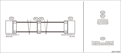
WIRING DIAGRAM:
NOTE:
For the coupling connector, refer to “WIRING SYSTEM”.
BSD/RCTA system Blind Spot Detection/Rear Cross Traffic Alert > WIRING DIAGRAM">
| STEP | CHECK | YES | NO |
1.CHECK DTC.
Read the DTC. Read Diagnostic Trouble Code (DTC) > OPERATION">
Is DTC B2350 displayed? (Current malfunction)
Diagnostic Procedure with Diagnostic Trouble Code (DTC) > DTC B2350 REAR RADAR COMMUNICATION ERROR BETWEEN MASTER AND SLAVE">Go to Step 2.
Even if DTC is displayed, the circuit has returned to a normal condition at this time. Reproduce the failure, and then perform the diagnosis again.
NOTE:
In this case, temporary poor contact of connector, temporary open or short circuit of harness may be the cause.
2.CHECK HARNESS (OPEN CIRCUIT).
1) Disconnect the radar sensor connectors LH and RH.
2) Using a tester, measure the resistance between radar sensor RH connector (harness side) and radar sensor LH connector (harness side).
Connector & terminal
(R25) No. 1 — (R61) No. 1:
(R25) No. 6 — (R61) No. 6:
Is the resistance less than 1 ??
Diagnostic Procedure with Diagnostic Trouble Code (DTC) > DTC B2350 REAR RADAR COMMUNICATION ERROR BETWEEN MASTER AND SLAVE">Go to Step 3.
Repair the open circuit of harness between radar sensor RH connector and radar sensor LH connector.
3.CHECK HARNESS (SHORT BETWEEN LINES, GROUND SHORT CIRCUIT).
Using a tester, measure the resistance between radar sensor LH connectors (harness side) and the resistance between radar sensor LH connector (harness side) and chassis ground.
Connector & terminal
(R25) No. 1 — (R25) No. 6:
(R25) No. 1 — Chassis ground:
(R25) No. 6 — Chassis ground:
Is the resistance 1 M? or more?
Diagnostic Procedure with Diagnostic Trouble Code (DTC) > DTC B2350 REAR RADAR COMMUNICATION ERROR BETWEEN MASTER AND SLAVE">Go to Step 4.
Repair the short circuit of harness between radar sensor RH connector and radar sensor LH connector.
4.CHECK HARNESS (SHORT CIRCUIT TO POWER SUPPLY).
1) Turn the ignition switch to ON.
2) Using a tester, measure the voltage between radar sensor LH connector (harness side) and chassis ground.
Connector & terminal
(R25) No. 1 (+) — Chassis ground (−):
(R25) No. 6 (+) — Chassis ground (−):
Is the voltage less than 1 V?
Diagnostic Procedure with Diagnostic Trouble Code (DTC) > DTC B2350 REAR RADAR COMMUNICATION ERROR BETWEEN MASTER AND SLAVE">Go to Step 5.
Repair the short to power supply in harness between radar sensor RH connector and radar sensor LH connector.
5.CHECK RADAR SENSOR. (INTERNAL IMPEDANCE).
Using a tester, measure the resistance between radar sensor LH connectors (module side) and the resistance between radar sensor RH connectors (module side).
Connector & terminal
(R25) No. 1 — (R25) No. 6:
(R61) No. 1 — (R61) No. 6:
Is the resistance approximately 120 ??
Diagnostic Procedure with Diagnostic Trouble Code (DTC) > DTC B2350 REAR RADAR COMMUNICATION ERROR BETWEEN MASTER AND SLAVE">Go to Step 6.
Replace the radar sensor RH or radar sensor LH. Radar Sensor">
6.CHECK BSD/RCTA.
1) Restore the vehicle to its original state.
2) Perform the Clear Memory Mode. Clear Memory Mode">
3) Perform the Inspection Mode. Inspection Mode">
Is DTC B2350 displayed? (Current malfunction)
Replace the radar sensor on the side that displayed the DTC. Radar Sensor">
Even if DTC is displayed, the circuit has returned to a normal condition at this time. Reproduce the failure, and then perform the diagnosis again.
NOTE:
In this case, temporary poor contact of connector, temporary open or short circuit of harness may be the cause.
 Dtc b2329 rear radar axis alignment incomplete
Blind Spot Detection/Rear Cross Traffic Alert (DIAGNOSTICS) > Diagnostic Procedure with Diagnostic Trouble Code (DTC)DTC B2329 REAR RADAR AXIS ALIGNMENT INCOMPLETEDTC DETECTING CONDITION:Axis adjus ...
 Dtc u0155 lost communication with instrument panel cluster (ipc) control module
Blind Spot Detection/Rear Cross Traffic Alert (DIAGNOSTICS) > Diagnostic Procedure with Diagnostic Trouble Code (DTC)DTC U0155 LOST COMMUNICATION WITH INSTRUMENT PANEL CLUSTER (IPC) CONTROL MODULED ...
Other materials:
Removal
HVAC SYSTEM (HEATER, VENTILATOR AND A/C) > Heater and Cooling UnitREMOVALCAUTION:Before handling the airbag system components, refer to “CAUTION” of “General Description” in “AIRBAG SYSTEM”. General Description > CAUTION">1. Disconnect the ground ca ...
Inspection
COMMUNICATION SYSTEM > Relay and FuseINSPECTION1. CHECK FUSE1. Remove the fuse and check visually.2. If the fuse is blown out, replace the fuse.2. CHECK RELAY1. Check the resistance between relay terminals.Terminal No.Inspection conditionsSpecificationCircuit1 — 2Always1 M? or more1 — 2Apply ...
Removal
GLASS/WINDOWS/MIRRORS > Rear Regulator and Motor AssemblyREMOVAL1. Disconnect the ground cable from battery. NOTE">2. Remove the trim panel - rear door. Door Trim > REMOVAL">3. Remove the sealing cover - rear door. Rear Sealing Cover > REMOVAL">4. Remove the glass ...
