Subaru Crosstrek Service Manual: Dtc b2286 engine speed signal(without auto start stop)
KEYLESS ACCESS WITH PUSH BUTTON START SYSTEM (DIAGNOSTICS) > Diagnostic Procedure with Diagnostic Trouble Code (DTC)
DTC B2286 ENGINE SPEED SIGNAL(WITHOUT Auto Start Stop)
DTC detecting condition:
When the engine speed signal transmitted from the ECM via solid line and the engine speed signal transmitted from the ECM via CAN communication line do not match.
Trouble symptom:
Cannot start the engine, or the engine stops after starting.
CAUTION:
For replacement procedure of keyless access CM, refer to the “REGISTRATION MANUAL FOR IMMOBILIZER” provided as a separate volume.
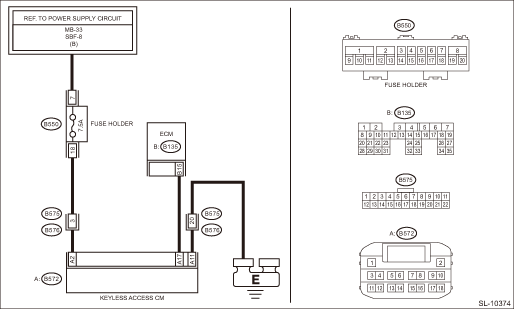
Wiring diagram:
Push button start system Push Button Start System > WIRING DIAGRAM">
| STEP | CHECK | YES | NO |
1.CHECK LAN SYSTEM.
Inspect LAN system. Basic Diagnostic Procedure > PROCEDURE">
Is LAN system normal?
Diagnostic Procedure with Diagnostic Trouble Code (DTC) > DTC B2286 ENGINE SPEED SIGNAL(WITHOUT Auto Start Stop)">Go to Step 2.
Perform the inspection according to the diagnosis for LAN system.
2.CHECK COMBINATION METER.
Confirm that the speedometer is displayed normally.
Is the meter display normal?
Diagnostic Procedure with Diagnostic Trouble Code (DTC) > DTC B2286 ENGINE SPEED SIGNAL(WITHOUT Auto Start Stop)">Go to Step 3.
Perform the diagnosis for the engine. Basic Diagnostic Procedure > PROCEDURE">
3.CHECK CURRENT DATA.
Check the current data display of «Keyless Access with Push Button Start» using Subaru Select Monitor. Read Current Data">
• «Engine speed»
Can the data be read normally?
Even if DTC is displayed, the circuit has returned to a normal condition at this time. Reproduce the failure, and then perform the diagnosis again.
NOTE:
In this case, temporary poor contact of connector, temporary open or short circuit of harness may be the cause.
Diagnostic Procedure with Diagnostic Trouble Code (DTC) > DTC B2286 ENGINE SPEED SIGNAL(WITHOUT Auto Start Stop)">Go to Step 4.
4.CHECK HARNESS (OPEN CIRCUIT).
1) Disconnect the keyless access CM connector.
2) Disconnect the ECM connector.
3) Using a tester, measure the resistance between the keyless access CM connector and ECM connector.
Connector & terminal
(B572) No. 17 — (B135) No. 15:
Is the resistance less than 1 ??
Diagnostic Procedure with Diagnostic Trouble Code (DTC) > DTC B2286 ENGINE SPEED SIGNAL(WITHOUT Auto Start Stop)">Go to Step 5.
Repair or replace the open circuit of harness.
5.CHECK HARNESS (GROUND SHORT CIRCUIT).
Using a tester, measure the resistance between the keyless access CM connector and chassis ground.
Connector & terminal
(B572) No. 17 — Chassis ground:
Is the resistance 10 k? or more?
Diagnostic Procedure with Diagnostic Trouble Code (DTC) > DTC B2286 ENGINE SPEED SIGNAL(WITHOUT Auto Start Stop)">Go to Step 6.
Repair or replace the short circuit of the harness.
6.CHECK HARNESS.
1) Connect the keyless access CM connector and ECM connector.
2) Using the Subaru Select Monitor, measure the waveform between the keyless access CM connector and chassis ground.
Connector & terminal
(B572) No. 17 — Chassis ground:
Does the pulse stop when the engine is stopped, and does the pulse generate when the engine is started?
Replace the keyless access CM. Keyless Access CM">
Perform the diagnosis for the engine. Basic Diagnostic Procedure > PROCEDURE">
 Dtc b2285 steering lock position signal correlation
KEYLESS ACCESS WITH PUSH BUTTON START SYSTEM (DIAGNOSTICS) > Diagnostic Procedure with Diagnostic Trouble Code (DTC)DTC B2285 STEERING LOCK POSITION SIGNAL CORRELATIONDTC detecting condition:When t ...
 Dtc b228a engine speed signal(with auto start stop)
KEYLESS ACCESS WITH PUSH BUTTON START SYSTEM (DIAGNOSTICS) > Diagnostic Procedure with Diagnostic Trouble Code (DTC)DTC B228A ENGINE SPEED SIGNAL(WITH Auto Start Stop)DTC detecting condition:When t ...
Other materials:
Key replacement
Your key number plate will be required if
you ever need a replacement key made.
Any new key must be registered for use
with your vehicle's immobilizer system
before it can be used. The maximum
number of keys that can be registered
for use with one vehicle is as follows.
Four (models with ...
Diagnostic procedure with phenomenon
EyeSight (DIAGNOSTICS) > Diagnostics with PhenomenonDIAGNOSTIC PROCEDURE WITH PHENOMENON1. TEMPORARY STOP OF EyeSightPhenomenonCheck ItemReference1Temporary stop occurs frequently.EyeSight temporary stop indicator illuminates frequently.(1) Check EyeSight temporary stop code. EyeSight Temporary C ...
License plate light
1. The license plate light must be pushed
inwards, then pulled out to be removed.
2. Turn the bulb socket counterclockwise
and pull out the socket.
3. Pull the bulb out of the socket.
4. Install a new bulb.
5. Reinstall the bulb socket and the
license plate light cover. ...
