Subaru Crosstrek Service Manual: Dtc b2284 brake signal correlation
KEYLESS ACCESS WITH PUSH BUTTON START SYSTEM (DIAGNOSTICS) > Diagnostic Procedure with Diagnostic Trouble Code (DTC)
DTC B2284 BRAKE SIGNAL CORRELATION
DTC detecting condition:
When the brake signal transmitted via the hard wire and the brake signal transmitted from body integrated unit via CAN communication line do not match.
Trouble symptom:
CAUTION:
For replacement procedure of keyless access CM, refer to the “REGISTRATION MANUAL FOR IMMOBILIZER” provided as a separate volume.
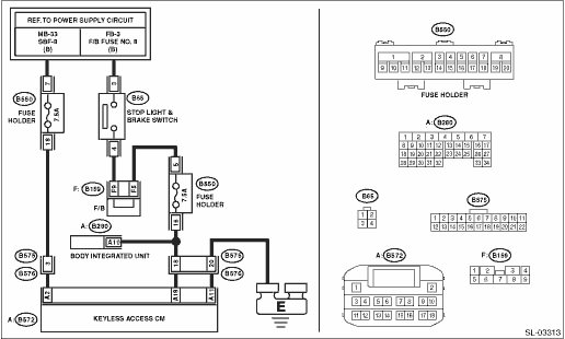
Wiring diagram:
Stop light system Stop Light System > WIRING DIAGRAM">
Push button start system Push Button Start System > WIRING DIAGRAM">
| STEP | CHECK | YES | NO |
1.CHECK LAN SYSTEM.
Inspect LAN system. Basic Diagnostic Procedure > PROCEDURE">
Is LAN system normal?
Diagnostic Procedure with Diagnostic Trouble Code (DTC) > DTC B2284 BRAKE SIGNAL CORRELATION">Go to Step 2.
Perform the inspection according to the diagnosis for LAN system.
2.CHECK CURRENT DATA.
Check the current data display of «Keyless Access with Push Button Start» using Subaru Select Monitor. Read Current Data">
• «Stop light SW»
Is DTC displayed normally according to the brake pedal operation?
Diagnostic Procedure with Diagnostic Trouble Code (DTC) > DTC B2284 BRAKE SIGNAL CORRELATION">Go to Step 3.
Check the stop light system.
3.CHECK CURRENT DATA.
Confirm the current data display of «Body Control» using Subaru Select Monitor. Read Current Data">
• «Stop light SW»
Is DTC displayed normally according to the brake pedal operation?
Diagnostic Procedure with Diagnostic Trouble Code (DTC) > DTC B2284 BRAKE SIGNAL CORRELATION">Go to Step 4.
Check body integrated unit Basic Diagnostic Procedure > PROCEDURE"> and the stop light switch circuit.
4.CHECK FUSE.
Check the fuse. Relay and Fuse">
Is the fuse OK?
Diagnostic Procedure with Diagnostic Trouble Code (DTC) > DTC B2284 BRAKE SIGNAL CORRELATION">Go to Step 5.
Replace the fuse. When the replaced fuse is blown immediately, check the power supply circuit for short-circuited.
5.CHECK HARNESS.
1) Disconnect the keyless access CM connector.
2) Using a tester, measure the voltage between keyless access CM connectors.
Connector & terminal
(B572) No. 2 (+) — Chassis ground (−):
Is the voltage 9.5 — 16 V?
Diagnostic Procedure with Diagnostic Trouble Code (DTC) > DTC B2284 BRAKE SIGNAL CORRELATION">Go to Step 6.
Check the power supply circuit.
6.CHECK HARNESS.
Using a tester, measure the resistance between the keyless access CM connector and chassis ground.
Connector & terminal
(B572) No. 11 — Chassis ground:
Is the resistance less than 1 ??
Diagnostic Procedure with Diagnostic Trouble Code (DTC) > DTC B2284 BRAKE SIGNAL CORRELATION">Go to Step 7.
Repair or replace the open circuit of harness.
7.CHECK HARNESS.
1) Disconnect the stop light switch connector.
2) Using a tester, measure the resistance between the keyless access CM connector and stop light switch connector.
Connector & terminal
(B572) No. 18 — (B65) No. 4:
Is the resistance less than 1 ??
Diagnostic Procedure with Diagnostic Trouble Code (DTC) > DTC B2284 BRAKE SIGNAL CORRELATION">Go to Step 8.
Repair or replace the open circuit of harness.
8.CHECK HARNESS.
Using a tester, measure the resistance between the keyless access CM connector and chassis ground.
Connector & terminal
(B572) No. 18 — Chassis ground:
Is the resistance 10 k? or more?
Diagnostic Procedure with Diagnostic Trouble Code (DTC) > DTC B2284 BRAKE SIGNAL CORRELATION">Go to Step 9.
Repair or replace the short circuit of the harness.
9.CHECK HARNESS.
Using a tester, measure the voltage between the keyless access CM connector and chassis ground when the brake pedal is depressed.
Connector & terminal
(B572) No. 18 (+) — Chassis ground (−):
Does the voltage change as follows? Brake pedal not depressed: 1 V or less > Brake pedal depressed: 11 — 14 V
Replace the keyless access CM. Keyless Access CM > REMOVAL">
Check the power supply circuit of stop light switch.
 Dtc b2283 vehicle speed sensor
KEYLESS ACCESS WITH PUSH BUTTON START SYSTEM (DIAGNOSTICS) > Diagnostic Procedure with Diagnostic Trouble Code (DTC)DTC B2283 VEHICLE SPEED SENSORDTC detecting condition:Either of the following mal ...
 Dtc b2285 steering lock position signal correlation
KEYLESS ACCESS WITH PUSH BUTTON START SYSTEM (DIAGNOSTICS) > Diagnostic Procedure with Diagnostic Trouble Code (DTC)DTC B2285 STEERING LOCK POSITION SIGNAL CORRELATIONDTC detecting condition:When t ...
Other materials:
X-MODE
WARNING
When operating the Subaru Ascent with X-MODE engaged, always remain fully
attentive. Overestimating the system’s capabilities can lead to hazardous situations
and potentially serious accidents.
Use extreme caution when relying on the hill descent control function
in the Suba ...
General diagnostic table Inspection
WHEEL AND TIRE SYSTEM > General Diagnostic TableINSPECTIONSymptomsPossible causeCorrective actionWheel is out of balance.Improperly inflated tire.Adjust the tire pressure.Uneven wearCheck the tire referring to “Abnormal tire wear” in this table, carry out the procedure and replace the ...
Rear combination lights
1. Using a Phillips screwdriver, remove
the upper and lower screws that secure
the rear combination light assembly.
2. Slide the rear combination light as-
11-38
sembly rearward and remove it from the
vehicle.
Rear side marker light
Rear turn signal light
Backup light
Sto ...
