Subaru Crosstrek Service Manual: Dtc b1811 open in driver s airbag dual stage - 2nd step
AIRBAG SYSTEM (DIAGNOSTICS) > Diagnostic Chart with Trouble Code
DTC B1811 OPEN IN DRIVER’S AIRBAG DUAL STAGE - 2ND STEP
Diagnosis start condition:
Ignition voltage is 10 V to 16 V.
DTC detecting condition:
• Airbag main harness circuit is open.
• Airbag module harness (driver’s side) circuit is open.
• Roll connector circuit is open.
• Driver’s airbag module is faulty.
• Airbag control module is faulty.
CAUTION:
Before performing diagnosis, refer to “CAUTION” in “General Description”. General Description > CAUTION">
NOTE:
Prior to starting work, prepare two AIRBAG RESISTORs (98299PA040).
Wiring diagram:
Airbag system Airbag System > WIRING DIAGRAM">
| STEP | CHECK | YES | NO |
1.CHECK POOR CONTACT OF CONNECTORS.
Check for poor contact of the connectors between the airbag control module and the driver’s airbag module.
Is there poor contact?
Replace the airbag harness.
Diagnostic Chart with Trouble Code > DTC B1811 OPEN IN DRIVER’S AIRBAG DUAL STAGE - 2ND STEP">Go to Step 2.
2.CHECK DRIVER’S AIRBAG MODULE.
1) Turn the ignition switch to OFF, disconnect the battery ground cable, and wait for 60 seconds or more.
2) Remove the driver’s airbag module.
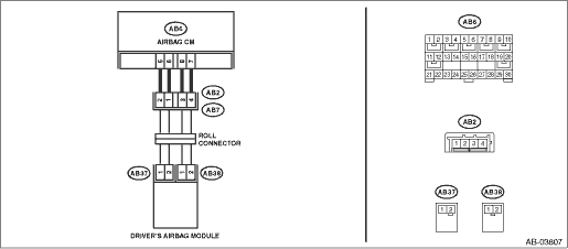
3) Connect the connector (1N) in the test harness N to the connector (AB38).
4) Connect the airbag resistor to the connector (2N) of test harness N.
5) Connect the connector (1Q) in the test harness Q to connector (AB37).
6) Connect the airbag resistor to the connector (2Q) in the test harness Q.
7) Connect the battery ground terminal and turn the ignition switch to ON.
Does the airbag warning light illuminate for six seconds and go off?
Replace the driver’s airbag module. Driver’s Airbag Module">
Diagnostic Chart with Trouble Code > DTC B1811 OPEN IN DRIVER’S AIRBAG DUAL STAGE - 2ND STEP">Go to Step 3.
3.CHECK ROLL CONNECTOR AND AIRBAG MAIN HARNESS (DRIVER’S AIRBAG HARNESS).
1) Turn the ignition switch to OFF, disconnect the battery ground cable, and wait for 60 seconds or more.
2) Remove the console front panel and disconnect the connector (AB9).
3) Disconnect the connector (AB66) from the driver’s knee airbag module.
4) Disconnect the airbag resistor from the connector (2N) in test harness N.
5) Disconnect the airbag resistor from the connector (2Q) of test harness Q.
6) Disconnect the connectors (AB6, AB17, AB18) from airbag control module.
7) Measure the resistance between connector (2N) terminals in test harness N.
Connector & terminal
(2N) No. 1 — (2N) No. 2:
Is the resistance less than 10 ??
Diagnostic Chart with Trouble Code > DTC B1811 OPEN IN DRIVER’S AIRBAG DUAL STAGE - 2ND STEP">Go to Step 5.
Diagnostic Chart with Trouble Code > DTC B1811 OPEN IN DRIVER’S AIRBAG DUAL STAGE - 2ND STEP">Go to Step 4.
4.CHECK ROLL CONNECTOR.
1) Remove the instrument panel lower cover and column cover, and disconnect the connector (AB7) from (AB2).
2) Measure the resistance between connector (2N) terminals in test harness N.
Connector & terminal
(2N) No. 1 — (2N) No. 2:
Is the resistance less than 10 ??
Replace the airbag main harness along with body harness.
Replace the roll connector. Roll Connector">
5.CHECK AIRBAG CONTROL MODULE.
1) Connect all connectors.
2) Clear the memory. Clear Memory Mode">
3) Perform the Inspection Mode. Inspection Mode">
4) Read the DTC. (Current malfunction) Read Diagnostic Trouble Code (DTC)">
Is DTC B1811 displayed?
Replace the airbag control module. Airbag Control Module">
Diagnostic Chart with Trouble Code > DTC B1811 OPEN IN DRIVER’S AIRBAG DUAL STAGE - 2ND STEP">Go to Step 6.
6.CHECK FOR ANY OTHER DTC ON DISPLAY.
Is any other DTC displayed?
Check DTC using “List of Diagnostic Trouble Code (DTC)”. List of Diagnostic Trouble Code (DTC)">
Finish the diagnosis.
 Dtc b1810 short in driver s airbag dual stage - 2nd step
AIRBAG SYSTEM (DIAGNOSTICS) > Diagnostic Chart with Trouble CodeDTC B1810 SHORT IN DRIVER’S AIRBAG DUAL STAGE - 2ND STEPDiagnosis start condition:Ignition voltage is 10 V to 16 V.DTC detectin ...
 Dtc b1812 short in driver s airbag dual stage - 2nd step (to ground)
AIRBAG SYSTEM (DIAGNOSTICS) > Diagnostic Chart with Trouble CodeDTC B1812 SHORT IN DRIVER’S AIRBAG DUAL STAGE - 2ND STEP (TO GROUND)Diagnosis start condition:Ignition voltage is 10 V to 16 V. ...
Other materials:
Operation
Driver's side
Passenger's side
SRS AIRBAGs deploy as soon as a collision occurs.
After deployment, SRS AIRBAGs start to deflate immediately so that the
driver's vision is not
obstructed.
The SRS airbags can function only when
the ignition switch is in the "ON" position.
Th ...
Removal
EXTERIOR BODY PANELS > Rear GateREMOVALCAUTION:The panel - rear gate is heavy. When removing and installing it, always work in a team of two or more persons.1. REAR GATE PANEL1. Disconnect the ground cable from battery. NOTE">2. Remove the trim panel - rear gate. Rear Gate Trim > REM ...
Removal
LIGHTING SYSTEM > Tail/Stop Light BulbREMOVAL1. CROSSTREK MODEL1. Disconnect the ground cable from battery. NOTE">2. Remove the light assembly - rear combination.CAUTION:Be careful not to damage the clips.(1) Release the bolts and clips, then pull out the light assembly - rear combinatio ...
