Subaru Crosstrek Service Manual: Dtc b1807 short in passenger s airbag (to ground)
AIRBAG SYSTEM (DIAGNOSTICS) > Diagnostic Chart with Trouble Code
DTC B1807 SHORT IN PASSENGER’S AIRBAG (TO GROUND)
Diagnosis start condition:
Ignition voltage is 10 V to 16 V.
DTC detecting condition:
• Airbag main harness circuit is shorted to ground.
• Airbag module harness (passenger’s side) circuit is shorted to ground.
• Passenger’s airbag module is faulty.
• Airbag control module is faulty.
CAUTION:
Before performing diagnosis, refer to “CAUTION” in “General Description”. General Description > CAUTION">
Wiring diagram:
Airbag system Airbag System > WIRING DIAGRAM">
| STEP | CHECK | YES | NO |
1.CHECK POOR CONTACT OF CONNECTORS.
Check for poor contact of the connectors between the airbag control module and the passenger’s airbag module.
Is there poor contact?
Replace the airbag harness.
Diagnostic Chart with Trouble Code > DTC B1807 SHORT IN PASSENGER’S AIRBAG (TO GROUND)">Go to Step 2.
2.CHECK AIRBAG MAIN HARNESS (PASSENGER’S AIRBAG HARNESS).
1) Turn the ignition switch to OFF, disconnect the battery ground cable, and wait for 60 seconds or more.
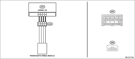
2) Disconnect the connectors (AB7) and (AB2).
3) Disconnect the connector (AB66) from the driver’s knee airbag module.
4) Disconnect the connectors (AB6, AB17, AB18) from airbag control module.
5) Disconnect the passenger’s airbag module connector (AB9).
6) Using a probe, measure the resistance between the connector (AB9) and chassis ground. General Description > PREPARATION TOOL">
CAUTION:
When measuring the resistance, make sure that the probe is inserted from the back side (harness side) of the connector. Also, do not insert the probe forcibly.
Connector & terminal
(AB9) No. 1 — Chassis ground:
(AB9) No. 2 — Chassis ground:
Is the resistance 1 M? or more?
Diagnostic Chart with Trouble Code > DTC B1807 SHORT IN PASSENGER’S AIRBAG (TO GROUND)">Go to Step 3.
Replace the airbag main harness along with body harness.
3.CHECK AIRBAG CONTROL MODULE.
1) Connect the connectors (AB6, AB17, AB18) and the airbag control module.
2) Using a probe, short the terminals No. 1 and No. 2 of connector (AB9). General Description > PREPARATION TOOL">
CAUTION:
When shorting the terminals, make sure that the probe is inserted from the back side (harness side) of the connector. Also, do not insert the probe forcibly.
Connector & terminal
(AB9) No. 1 — (AB9) No. 2:
3) Connect the battery ground terminal and turn the ignition switch to ON.
4) Perform the Inspection Mode. Inspection Mode">
5) Read the DTC. (Current malfunction) Read Diagnostic Trouble Code (DTC)">
Is DTC B1807 displayed?
Replace the airbag control module. Airbag Control Module > REMOVAL">
Diagnostic Chart with Trouble Code > DTC B1807 SHORT IN PASSENGER’S AIRBAG (TO GROUND)">Go to Step 4.
4.CHECK PASSENGER’S AIRBAG MODULE.
1) Turn the ignition switch to OFF, disconnect the battery ground cable, and wait for 60 seconds or more.
2) Release the short circuit of connector (AB9).
3) Connect the passenger’s airbag module connector (AB9).
4) Connect the connectors (AB7) and (AB2).
5) Connect the connector (AB66) to the driver’s knee airbag module.
6) Connect the battery ground terminal and turn the ignition switch to ON.
7) Perform the Inspection Mode. Inspection Mode">
8) Read the DTC. (Current malfunction) Read Diagnostic Trouble Code (DTC)">
Is DTC B1807 displayed?
Replace the passenger’s airbag module. Passenger’s Airbag Module > REMOVAL">
Diagnostic Chart with Trouble Code > DTC B1807 SHORT IN PASSENGER’S AIRBAG (TO GROUND)">Go to Step 5.
5.CHECK FOR ANY OTHER DTC ON DISPLAY.
Is any other DTC displayed?
Check DTC using “List of Diagnostic Trouble Code (DTC)”. List of Diagnostic Trouble Code (DTC)">
Finish the diagnosis.
 Dtc b1806 open in passenger s airbag
AIRBAG SYSTEM (DIAGNOSTICS) > Diagnostic Chart with Trouble CodeDTC B1806 OPEN IN PASSENGER’S AIRBAGDiagnosis start condition:Ignition voltage is 10 V to 16 V.DTC detecting condition:• ...
 Dtc b1808 short in passenger s airbag (to +b)
AIRBAG SYSTEM (DIAGNOSTICS) > Diagnostic Chart with Trouble CodeDTC B1808 SHORT IN PASSENGER’S AIRBAG (TO +B)Diagnosis start condition:Ignition voltage is 10 V to 16 V.DTC detecting condition ...
Other materials:
Location
LIGHTING SYSTEM > Relay and FuseLOCATIONMain fuse boxHeadlight relay (HI)(A)Headlight relay (LO)(B)Fuse 15 A (daytime running light relay)(C)Fuse 30 A (combination light LH/RH)(D)Fuse 20 A (spot map light, room light, ignition switch illumination (immobilizer antenna))(E)Fuse 15 A (tail and illum ...
Auto light sensor sensitivity setting
1. Perform the preparation steps according
to "Preparation for car settings"
2. Operate the " " or "
" switch to
select the "Auto Light Sensor" item. Then
push the button.
3. The current setting will be displayed.
Push the button to enter the
selection
mode.
4. Selec ...
Component
EyeSight > General DescriptionCOMPONENT1. STEREO CAMERA(1)Shim (washer)(4)Stereo camera cover ASSYTightening torque: N·m (kgf-m, ft-lb)(2)Camera plate(5)CapT:5.5±1.0 (0.56±0.10, 4.1±0.7)(3)Stereo camera ...
