Subaru Crosstrek Service Manual: Dtc b1613 front sub sensor rh initialization error
AIRBAG SYSTEM (DIAGNOSTICS) > Diagnostic Chart with Trouble Code
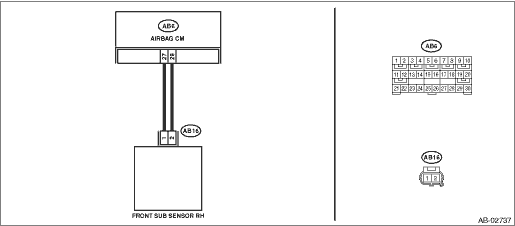
DTC B1613 FRONT SUB SENSOR RH INITIALIZATION ERROR
Diagnosis start condition:
Ignition voltage is 10 V to 16 V.
DTC detecting condition:
• Open or short circuit in harness of front sensor bus (RH)
• Front sub sensor (RH) is faulty.
• Airbag control module is faulty.
CAUTION:
Before performing diagnosis, refer to “CAUTION” in “General Description”. General Description > CAUTION">
Wiring diagram:
Airbag system Airbag System > WIRING DIAGRAM">
| STEP | CHECK | YES | NO |
1.CHECK POOR CONTACT OF CONNECTORS.
Check for poor contact of the connectors (AB6, AB16) between the airbag control module and the front sub sensor (RH).
Is there poor contact?
Replace the airbag main harness along with body harness.
Diagnostic Chart with Trouble Code > DTC B1613 FRONT SUB SENSOR RH INITIALIZATION ERROR">Go to Step 2.
2.CHECK AIRBAG MAIN HARNESS (FRONT SENSOR BUS RH).
1) Turn the ignition switch to OFF, disconnect the battery ground cable, and wait for 60 seconds or more.
2) Remove the instrument panel lower cover and column cover, and disconnect the connectors (AB7) and (AB2).
3) Remove the console front panel and disconnect the connector (AB9).
4) Disconnect the connectors (AB6, AB17, AB18) from airbag control module.
5) Connect the connector (1AG) in the test harness AG to the connectors (AB6, AB17, AB18).
6) Disconnect the connector (AB16) from the front sub sensor (RH), and then connect the connector (1H) in the test harness H to connector (AB16).
7) Measure the resistance between connector (4AG) in the test harness AG and connector (3H) in the test harness H.
Connector & terminal
(4AG) No. 14 — (3H) No. 5:
(4AG) No. 12 — (3H) No. 6:
Is the resistance less than 10 ??
Diagnostic Chart with Trouble Code > DTC B1613 FRONT SUB SENSOR RH INITIALIZATION ERROR">Go to Step 3.
Replace the airbag main harness along with body harness.
3.CHECK AIRBAG MAIN HARNESS (FRONT SENSOR BUS RH).
Measure the resistance between connector (4AG) in the test harness AG and chassis ground, and the resistance between connector (4AG) terminals in the test harness AG.
Connector & terminal
(4AG) No. 12 — Chassis ground:
(4AG) No. 14 — Chassis ground:
(4AG) No. 12 — (4AG) No. 14:
Is the resistance 1 M? or more?
Diagnostic Chart with Trouble Code > DTC B1613 FRONT SUB SENSOR RH INITIALIZATION ERROR">Go to Step 4.
Replace the airbag main harness along with body harness.
4.CHECK AIRBAG CONTROL MODULE.
1) Connect all connectors.
2) Clear the memory. Clear Memory Mode">
3) Perform the Inspection Mode. Inspection Mode">
4) Read the DTC. (Current malfunction) Read Diagnostic Trouble Code (DTC)">
Is DTC B1613 displayed?
Replace the front sub sensor (RH). Front Sub Sensor > REMOVAL"> Replace the airbag control module if not operating normally even after replacing the sensor. Airbag Control Module > REMOVAL">
Diagnostic Chart with Trouble Code > DTC B1613 FRONT SUB SENSOR RH INITIALIZATION ERROR">Go to Step 5.
5.CHECK FOR ANY OTHER DTC ON DISPLAY.
Is any other DTC displayed?
Check DTC using “List of Diagnostic Trouble Code”. List of Diagnostic Trouble Code (DTC)">
Finish the diagnosis.
 Dtc b1612 front sub sensor rh lost communication
AIRBAG SYSTEM (DIAGNOSTICS) > Diagnostic Chart with Trouble CodeDTC B1612 FRONT SUB SENSOR RH LOST COMMUNICATIONNOTE:For details on DTC B1612, refer to DTC B1613. Diagnostic Chart with Trouble Cod ...
 Dtc b1615 front sub sensor lh failure
AIRBAG SYSTEM (DIAGNOSTICS) > Diagnostic Chart with Trouble CodeDTC B1615 FRONT SUB SENSOR LH FAILUREDIAGNOSIS START CONDITION:Ignition voltage is 10 V to 16 V.DTC DETECTING CONDITION:Front sub sen ...
Other materials:
Caution
OCCUPANT DETECTION SYSTEM (DIAGNOSTICS) > General DescriptionCAUTION1. The occupant detection system (passenger seat only) control module and the occupant detection sensor are fixed to the seat cushion frame. Never remove the occupant detection control module or the occupant detection sensor from ...
Operation
INSTRUMENTATION/DRIVER INFO > Combination Meter SystemOPERATION1. SELF-DIAGNOSIS DISPLAY MODEThe self-diagnosis (checking of each meter, warning light, indicator light, illumination, LCD/TFT) of combination meter can be performed in the following procedure.1. ProcedureCAUTION:Perform the steps de ...
Specification
STARTING/CHARGING SYSTEMS(H4DO) > General DescriptionSPECIFICATIONItemSpecificationsVehicle modelCVTMTStarterTypeReduction typeModelM000T38571M000T33176ManufacturerMitsubishi ElectricVoltage and output12 V — 1.2 kW12 V — 1.0 kWDirection of rotationCounterclockwise (when observed from pinion)N ...
